Intro to Video Signals
Video Signals
| Video Standard | Image | Connectors | Signals Carried | Explanation |
|---|---|---|---|---|
| Radio Frequency (RF) | 
|
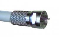
One F-type coax OR One RCA OR Two prongs |
Luminance (Y, H, V), Chrominance (C), Audio Left, Audio Right | RF (Radio Frequency) is a Frequency Modulated signal in the UHF band usually incoming from an antenna or long run cable. This signal contains modulated composite video and mono/stereo audio. It does a great job of transmitting a signal over very long distances over air or wire with little loss.
Most televisions feature an RF tuner and demodulator to handle RF input. The most common connector is the F-type (coax, like cable TV). Much older televisions (early 1980s and earlier) usually have two screws to fasten down a twin-lead antenna. Rarely they will have an RCA-type connector which expects RF input. Televisions with a rotary select dial usually indicates that it only supports RF input. Depending on the television, the RF tuner is usually connected to all inputs and may be designed to handle both 300 Ohm and 75 Ohm. The F-type connector is almost always expecting 75 Ohm input. Check the TV user guide or service manual to be sure. It will not harm the television to feed the wrong impedance, but the signal may be too weak to see. If the impedance from your console to the TV is mismatched (F-type is 75 Ohm and Twin-lead is 300 Ohm), you need a balun (transformer) – a very simple circuit and cheap to buy and works in both directions. |
| Composite Video | 
|
One RCA OR One BNC |
Luminance (Y, H, V), Chrominance (C) | Composite video is very common, and comes on almost every consumer TV made after 1990. Composite, as the name implies, is a complex signal. It was designed for NTSC, PAL, and SECAM broadcasting and contains the information for chrominance (hue and saturation), luminance (brightness), horizontal sync, and vertical sync all on one wire.
While it is often downplayed as inferior to other video signal types, it remained a standard for which many CRTs and game consoles were designed to handle. The quirks and lossiness of the signal were sometimes exploited in games to create useful effects such as smoothed colour dithering and fake transparency. Examples here on Genesis and SNES (nerdlypleasures.blogspot.ca) and here with the transparent tubes in Sonic 2 (youtube.com). On the other hand, visual defects such as dot crawl and jitter can be a real nuisance of interference between the 5 signals. Many consumer TVs have a "comb filter" designed to eliminate interference issues, but often times professional or broadcast monitors do not have a comb filter as studios often wanted to be able to see interference issues and eliminate them during broadcast. Composite supports up to 240p/480i resolution in NTSC and 288p/576i in PAL. |
| S-Video | 
|
One 4-pin Mini-DIN OR Two RCA OR Two BNC |
Luminance (Y, H, V) Chrominance (C) |
S-Video is derived from component video where Y retains the same level of fidelity along with synchronization signals, but the U & V signals are quadrature modulated and sent as one signal down the second wire.
S-video is considered a higher quality signal and is well supported by hardware from the mid 1990s and later.
|
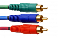
| Component YPbPr | placeholder | Three RCA | Luminance (Y, H, V) Pb (blue difference from Y) Pr (red difference from Y) |
YPbPr splits video out to 3 different connectors, making it better quality than S-Video. "Y" transmits brightness information (Luma) and horizontal/vertical sync, "Pb" transmits the difference between the blue color signal and Y, and "Pr" transmits the difference between the blue color signal and Y.
Component is a very high quality video signal derived from RGB. Transmission bandwidth (and storage) is reduced by a large margin via exploiting the limitations of human vision and relationships between colour attributes to its advantage. The formulae for deriving the weighted signals are as follows: Y = 0.3R + 0.59G + 0.11B U = 0.493(B - Y) V = 0.877(R - Y) Green information is not sent as it can be derived from these relationships. There is also a similar YCbCr that is a digitally encoded.
|
| RGB | 
|
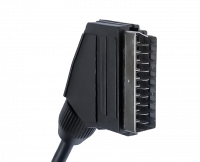
One SCART OR One JP-21 OR Three to Five RCA OR Three to Five BNC |
Uses different types of sync. | RGB is the best quality video you can get, as it requires no transcoding or changing of the color space and it is the same format that the electron gun uses to make the image displayed for CRTs. Note that the difference between the sync separation types is often not noticeable, but the more separation the less chance of interference. See the Types of Sync for in-depth information. Choose the most separated option which your equipment supports (depending on cable availability). |
