LaserActive:Pioneer Laseractive CLD-A100 Various Issues and Solutions
The biasing network design of the Laseractive makes it prone to major damage should one of it's voltage rails become absent. This page details various failures and fixes known for the Laseractive player to assist others in their repair efforts.
SERVICE POWER SUPPLY FIRST
Ensuring the power supply is outputting proper voltages is the key to resolving most Laseractive failures and thus should be the first item serviced before any other board in the CLD-A100.
If the power supply has not had the capacitors replaced, do so as soon as possible. Adding fresh solder to the three ribbon cable connectors, as well as the various power transistors will mitigate cold solder joint issues that would result in loss of a voltage rail, especially Q302, which is the switch for the -5V rail.
Replace the various ICP (in circuit protector) parts with new ones, as there have been reports of some beginning to behave like a diode (one way only conduction). Depending on the revision of power supply, different values of ICP's are listed on the board silkscreen, but best practice is to use the most "up to date" version:
- IC101, IC102 - ICP-N20
- IC201 - ICP-N25
- IC202, 301 - ICP-N50
- IC204 - ICP-N50 (present on later revisions)
On later revisions of the power supply, an additional ICP-N50 was added for the +5V rail on INTF. This extra ICP is STRONGLY ADVISED to be added if not present. See Power Supply ICP Mod for details.
Resistors R301-R304 are prone to failure that result in the loss of the -5V rail. The values are not in the service manual schematic, but have been determined to be:
- R301 - 2.2k
- R302 - 2.7k
- R303 - 220
- R304 - 220
It is advisable to use at least 1/8W resistors.
After servicing and verifying that the voltages are proper, proceed with further troubleshooting.
Mains Fuse Fails when Powered On
This issue could be due to the Flyback Primary side power BJT, Q001. Check Continuity between Pins 1-2, 2-3 and 1-3. If the transistor is short, replace it and the mains fuse. Verify continuity before applying power again. Additionally, there could be an issue with other boards in the unit, causing the primary side of the power supply flyback to short, so some additional troubleshooting will likely be required.
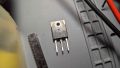
Q001

No display or dim display; LD/CD buttons and tray may still function
The most likely root cause of dim/no display is loss of the +5V rail, likely caused by a PAC with shorted voltage rails. Replace ICP's on the power supply and bench test the power supply before reapplying power.
If the LD/CD buttons/tray still appear to function, then the system most likely lost the supplemental ICP-N50 fuse (IC204), which protects the Switched 5V rail to the INTF board. As above, service the power supply and test as directed before reinserting into the player and operating.
No analog audio from Laserdisc
If the -5V rail is lost, the analog audio demodulator, IC1 (CA0002AM) on the VIDEO board will overheat and possibly fail. Service the PSU first, then if audio is still gone, the CA0002AM IC will need to be replaced.
Spindle Motor Won't Spin LD's or CD's (Belts have been replaced and no Power Supply Faults)
Replace IC611 on the VIDEO board.
Optical Pickup Emits Smoke After Player Turned on
If the either the +14 or -14V voltage rail is missing, this will cause a voltage imbalance on the focus/tracking amplifier and cause the pickup to emit smoke. Ensure that the +/- 14V rail ICP's are replaced on the Power Supply, as well as the two ICP-N10's on FTSB. .
Additionally, it is recommended to clean and reflow on FTSB: IC802, IC804 as well as the pins for J801 (the ribbon cable which connects to the power supply).
Discs spin at maximum speed, no playback
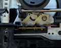
If discs will spin upon pressing play, but seem to spin at maximum speed with no playback, there is most likely an issue with the spindle motor speed sensing circuit. Ensure R111 and R110 measure 1k Ohm (+/- 5%) and that R109 is less than 1 ohm (actual value ~0.05 ohm, will show as "shorted" if checking for continuity). Additionally, check whether IC611 (4558D) on the VIDEO board is not damaged.
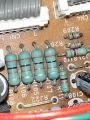
Close-up of Spindle Motor Current Sense Resistors on SYPS

CD's do not spin/CD's Spin but stop after several seconds
If Laserdiscs can play but CD's cannot spin, or if CD playback is possible, but stops after several seconds, one possible root cause is a missing signal between the EFM Decoder circuitry on INTF and the Mechacon on CONT. It is recommended to reflow the solder joints for the rigid right angle connectors that on the CONT board that connect to INTF.
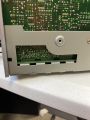
CONT Right Angle Connector pins

Laserdiscs do not spin
This is most likely due to a worn/loose carriage motor assembly belt. Replacing the belt should provide enough tension for the motor system to clamp the laserdisc, but it is also highly recommended to replace the capacitors and ICP fuses on the power supply as well.
PAC N1/N10 crashes after several seconds
If an ICP-N50 has been added but connected to the wrong voltage rail (i.e. EVER 5V instead of SW +5V), this will cause the PAC-N1/10 to crash as well as PAC-S1/10 to run at abnormally high temperatures.
Carriage Motor/Pickup rapidly moves back and forth, cannot complete startup operation
This is most likely due to the various switches that the player uses to determine carriage position as well as pickup assembly position being out of place or shorted/missing. If the carriage assembly has been disassembled (such as for relubrication), ensure that the three rocker arms that are controlled by the large black cam gear are properly positioned. If the pickup assembly has been removed, ensure that the two rocker arms that are actuated by the pickup rail are properly positioned.
Additionally, ensure that the ribbon cable that comes from the front of the carriage assembly is properly installed to the FTSB board with no pins shorting to each other. The red line on the ribbon cable indicates "pin 1."
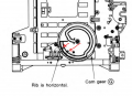
Cam Gear Switch Diagram
Pickup Assembly Rocker Arm Positions

