SMS II Video Mods
The Sega Master System II was a cost-reduced successor to the original Master System, and was introduced during the early 1990s as a budget alternative to the 16-bit Genesis/Mega Drive. In addition to eliminating the reset button, expansion port and Sega Card slot, it also did away with the AV and RGB outputs in favor of only having RF out. While this may have been acceptable at the time, especially since the SMS II was marketed as a budget console, nowadays this makes it more difficult to connect the console to monitors such as Sony PVMs or modern upscalers.
Fortunately, the SMS II is capable of being easily modified for composite, S-video or RGB outputs.
Overview
Despite only having RF output, the Master System II generates its video the same way as all other Master System consoles. Its VDP outputs RGB, which is then wired to a video encoder chip. The encoder then outputs a composite video signal which is fed into an RF modulator alongside the audio signal. On the NTSC SMS II, the video signal going into the modulator is already suitable for outputting directly to a display, so composite video can be simply tapped from the appropriate RF modulator pin after removing a pulldown resistor. A similar process also goes for the audio signal. Both of these can be done without removing the RF modulator, though the modulator can be removed in order to facilitate a no-cut mod.
Getting S-video output requires more work, especially in the case of the CXA1145 encoder used in all NTSC SMS IIs and some PAL models. While it generates separate chroma and luma signals necessary for S-video, these were intended to be fed back into the encoder in order to generate composite video and were not designed for connection to an external display. Nevertheless, it is possible using external circuitry to get a usable S-video output from this encoder. The Fujitsu MB3514 used in later PAL SMS IIs is capable of outputting proper S-video, requiring only a 75 ohm resistor on both the chroma and luma signals.
RGB output is even easier to attain since both the CXA1145 and MB3514 also output amplified RGB. Depending on the connector, no extra components are needed.
If you have a PAL SMS II and wish to have it output NTSC video, refer to this procedure here.
Note that the SMS II sold in France differs in that it only outputs RGB, and was bundled with a special SCART cable. It lacks a video encoder entirely as well as all of the associated support circuitry, so it cannot be easily modified for composite or S-video output. Because it shares the same motherboard as the NTSC SMS II, it is possible to repopulate these components to get composite, S-video and amplified RGB, but that is beyond the scope of this procedure.
Materials and Tools
Materials
- Leaded solder
- Hookup wire
- Flux
- Output connector(s) of choice (see procedure for details)
- Additional components (see procedure for details, this will vary depending on the particular installation)
Tools
- Soldering iron
- Flush cutters
- Wire strippers
- Desoldering iron or desoldering braid
- Cordless drill with step bit (depending on output connector selection)
- Multimeter
Procedure
- Flip over the Master System II and remove the five screws securing the shell. When all five screws have been removed, tilt the top shell towards the front to remove it. This is because there are two small tabs which hold the top shell in place alongside the screws.
- Unscrew the top RF shield and set it aside. Carefully remove the main board along with the bottom RF shield, then set the bottom shell and shielding aside.
- Once fully disassembled, the video mods can be installed. Follow the sections below depending on which outputs you wish to add.
Composite
Keeping RF Modulator
If you are retaining the RF modulator, solder a 75 ohm resistor and 220 uF capacitor in series onto pin 20 of the video encoder. It may help to place these components on a separate perfboard to avoid the risk of components shorting on other parts of the console. Solder a wire from the negative lead of the 220 uF capacitor to your output connector.
RF Modulator Removed
If the RF modulator is removed, you can use the existing composite video circuit on the board. For NTSC consoles, first remove resistor R70. This is a pulldown resistor intended for the RF modulator video input and will cause the image to be too dark. Once this is removed, video can be tapped from pin 2 of the RF modulator.
For PAL consoles, replace resistor R21 with a 75 ohm resistor, then remove resistor R29 completely. Optionally, upgrade C38 from 100 uF to 220 uF.
Audio
Audio can be tapped from pin 3 of the RF modulator and does not require any extra components. However, you may experience low or muffled audio because the signal was meant to be amplified by the RF modulator. To fix this, remove R27 (10k ohm pulldown) and replace R28 (8.2k ohm) with a 10 uF capacitor.
RGB
The video encoder provides amplified RGB that only requires a 75 ohm resistor and 220 uF capacitor for each signal. On NTSC consoles and older PAL consoles with Alex Kidd built-in, there are convenient solder points or vias on the board for RGB out, which are shown below. Consoles with the Fujitsu MB3514 encoder, namely ones with Sonic built-in, do not have these solder points present. On these consoles you will need to solder wires directly to the red, green and blue pins (pins 23, 22 and 21 respectively) of the encoder. On both encoders, composite sync can be obtained from pin 10, though this is TTL sync and cannot be used directly on some displays or upscalers. On NTSC consoles, composite sync can also be tapped from pin 7 of the unused DIN footprint.
If you will be using cables intended for a Genesis/Mega Drive, the RGB outputs can be directly connected to the output connector with no extra components, as these cables already have the 220 uF capacitors and 75 ohm resistors present. If a passive RGB cable is used (meaning the cable does not contain extra components), these capacitors and resistors will need to be added inside the console or the output will be too bright.
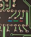
The underside of the NTSC board has these solder pads for RGB output.
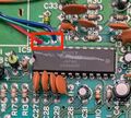
PAL boards with the Sony CXA1145 encoder have vias for RGB output.


S-video
Getting S-video will require more work in most SMS II consoles, since the CXA1145 encoder was not designed for proper S-video output.
For S-video on the CXA1145, you will require a standard NPN transistor and a 27 ohm resistor for the luma line, and a 75 ohm resistor and 220 uF capacitor for chroma. Chroma is located on pin 15, and requires the resistor and capacitor (positive to chip) in series to the S-Video port (pin 4, top left). Luma is a little more tricky, and requires pin 16 to be connected to the base pin of the transistor, and the emitter connected to a 27 ohm resistor to the S-Video port (pin 3, top right). Power for the collector pin can be obtained from pin 12 (5V) of the encoder (bottom left).
The following diagram is made by raelgc:

For consoles with the MB3514 encoder, S-video is much easier to obtain as this encoder was designed to drive S-video output. Both pins 15 and 16 require a 75 ohm resistor and 220 uF capacitor in series.
Output Connector Choices
9-Pin Mini-DIN
A good choice for an AV output connector on the SMS II is a 9-pin mini-DIN connector, which is used in the model 2 Genesis/Mega Drive. Not only are there a variety of cables which use this connector, but using this connector means that no extra holes need to be drilled in the console shell, preserving its original appearance. If you decide to use this connector, it is highly recommended to use it with the Consoles Unleashed breakout PCB, which has convenient solder pads and also has extra pads which can link the left and right audio pins together and even link them to the mono audio pin, which can allow you to use a Genesis 2/Mega Drive II RF switch for RF output. Adding this connector will require the removal of the RF modulator.
- Carefully desolder the RF modulator. The three pins connecting it to video, audio and 5V only have plated through-holes on the bottom so they are fairly easy to desolder. The ground lugs on the modulator casing connecting it to the ground plane require more effort so take your time. You can also use a thin pry tool to carefully pull the modulator off the board as you desolder it.
- Take a shielded 9-pin mini-DIN connector and place it upside down on the ground plane, lining up the connector with the RF jack hole and pushing it as close to the shell as possible. If lined up correctly, there will be enough clearance for cables to clear the RF hole.
- Tack down the back of the connector with a small blob of solder and check the alignment again. If you are still satisfied with the alignment, solder down the sides of the connector to the ground plane. Once the sides are soldered down, add more solder to the back so it is securely connected to the ground plane. Your solder joints should be smooth ramps and the connector should not move at all.
- Wire up the outputs to the mini-DIN or breakout PCB according to this pinout.
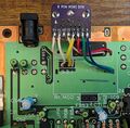
A completed mini-DIN install on an NTSC Master System II.
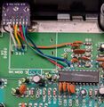
A completed mini-DIN install on a PAL Master System II.
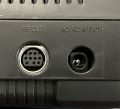
How the mini-DIN appears from the outside.


