Genesis:Model 2 RGB Bypass

| This page is an overview and doesn't have instructions for every motherboard revision. RGB bypassing a Genesis should be considered an "expert installation" and you'll likely need more information than what is provided here. It's recommended to install a pre-made Genesis:Triple Bypass Mod instead. |
Model 2 Genesis consoles do not require a modification for RGB output, only a cable. This page that describes how to bypass the Genesis internal RGB amp with a different one. All details are below, but this mod requires you to make irreversible modifications to your Genesis system.
Please make sure to read the main Genesis:Triple Bypass Mod page before proceeding to make sure that this mod is something you'd really like to do. You must read the sections about sync requirements and RGB cables, as it might change the way you approach this mod. Also, there are many different board revisions for the Genesis / Mega Drive and each will look different inside. Use these instructions as a basic guide, but you'll need to double check each detail on your own console.
Tools / Parts Needed:
You'll need a few tools for this mod:
- A RGB bypass solution (if using a Triple Bypass, use the Genesis:Triple Bypass Mod page instead)
- Excellent soldering skills
- Philips head screwdriver
- Soldering iron / solder / flux
- Thin gauge wire
- Small pick or "dental tool" to lifting pins
- Multimeter
Instructions
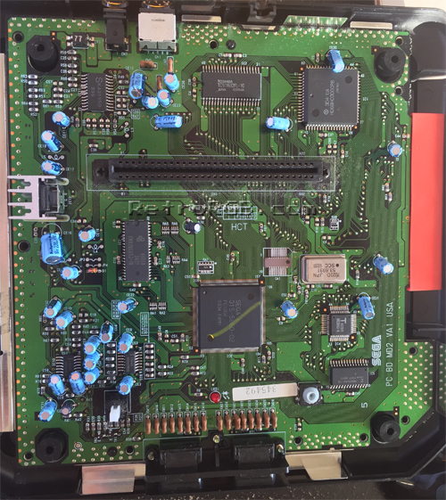
- Completely disassemble the console. Find a potential mounting locations for the bypass board, that are clear and free of all components.
- Find the main video chip. This model Genesis 2 has a VA1 motherboard installed and uses a Sega 315-5660-02 video chip.
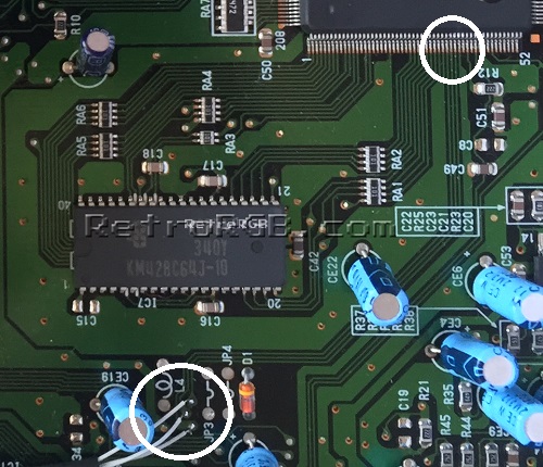
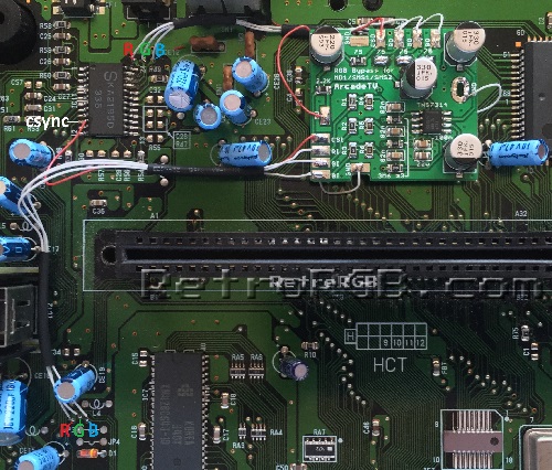
- Research the pinout of your Sega chip. The 315-5660-02 outputs RGB on pins 35, 36 and 37 (respectively). You can solder directly to the pins, however it's much easier to use your multimeter to trace the pins to an easier location. This board connects CSYNC directly to the video encoder in the image below, but you may find alternate points to solder to.
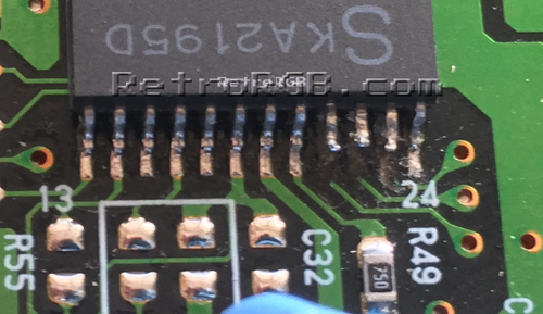
- Prepare the multi-out port to accept the new RGBs signals. Unfortunately, there are no components between the Sony CXA video encoder and the multi-out on this specific board, so the only way to disconnect the old signals is by cutting or lifting. You can cut the traces on the bottom of the multi-out, but it's preferable to lift the RGB-out pins 21, 22 and 23 to make the mod reversible. Note that in some Genesis revisions (such as this one), the Sony CXA chip is labeled as something different. As long as it looks the same, use a multimeter to confirm pins 21, 22 and 23 connect directly to the multi-out to verify that it's the correct chip before cutting/lifting.
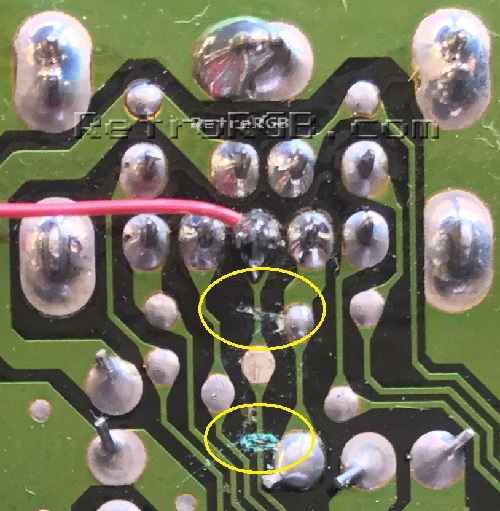
- Next you'll have to deal with CSYNC. In this VA1 motherboard, the sync pin #42 from the Sega 315-5660-02 is connected directly to both the "sync-in" pin 10 on the Sony video encoder and the multi-out; "sync-out" pin 11 isn't connected to anything. You can try lifting the pin from the CXA, but if you do, you'll disable composite video. In this case, it may be safer overall to cut the trace on the bottom of the multi-out. If you do cut it, use a multi-meter to verify the cut properly severed the line. This is also a good time to add a wire to the CSYNC pin, which will run to the bypass board
- After that, trim wires to length and connect the inputs and outputs of the bypass board. You'll also want to get CSYNC from pin 10 of the CXA chip, assuming you didn't cut any pins. It may be easier to solder RGB-out from the bypass board to vias on the motherboard. If your revision doesn't have those vias, you'll need to solder directly to the multi-out pins on the bottom of the motherboard.
- Re-assemble the entire console and make sure none of the wires are pinched by any of the shielding or plastic cover.


Summary / Tips
- If the screen is too dark, your RGB cable most likely has 75ohm resistors in the console-side of the cable. If that's the case, simply remove the resistors on the bypass board and bridge the connections (as shown in the above pic).
- If you're still getting any kind of jailbars or screen noise after performing this mod, there's some kind of interference. You can try using shielded cable for the mod, but on some model Genesis systems, there's just too much interference on the board itself. In this case, you may be able to lift the RGBs pins from the Sega 315-5660-02 and connect them directly to the bypass board. Doing this will disable composite video, or S-Video (if you've done that mod), so only do this as a last-resort option.