THS Video Amplifier Guide
The Texas Instruments THS7314 and THS7316 chips are SDTV video amplifiers designed specifically for analog video signals. They are commonly used in other mods, such as the Triple Bypass Mod, and as an RGB amplifier in retro game consoles.


Both the 7314 and 7316 are virtually identical, except for the analog video low-pass filter (LPF) In almost all cases, the THS7316 chip is recommended since it does not use the same LPF. Analog displays don't need one and almost every single digital solution will already include some kind of filtering. Adding a low-pass filter to video isn't a bad thing, but you loose detail when multiple filters are stacked on top of each other. For a detailed description, check out Voultar's post on Shmups. Here are the official pages for both amps - The datasheets are listed under the "technical documents" tab: THS7314 THS7316
The 7316 actually does have a LPF, but it's tuned to a higher frequency that doesn't affect SDTV signals, so when used with classic game consoles, it's as if it's not even there.
Parts Needed
- Soldering skills!
- Soldering iron / solder (rosin core solder recommended)
- Multimeter
- RGB Amplifier chip: The THS7316 is recommended, but if you need the LPF, use the THS7314
- Circuit board to mount the RGB amp
- Three 75 Ohm resistors, the lowest tolerance possible
- One 0.1uf Capacitor
Installation
The installation of both chips is identical. While the chips in this guide show the 7314, the same procedure is used for the 7316.
Both chips have 3 inputs/outputs, plus power and ground. The power is filtered by a capacitor and the output is regulated by 75 Ohm resistors. Using 75 Ohm resistors is important, as it provides the exact signal your display is expecting. Using resistors other than 75 Ohm could cause quality loss in the video output, among other unwanted side-effects. If you're using one of these amps in your game console, but find the output to be too bright, check the individual mod pages for more info, or simply add resistors to the input side of the amp, instead of changing the output resistance.
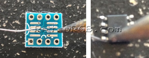
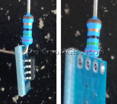
- First, start by adding solder to both the circuit board and the amp chip itself. Use your soldering iron to heat the pins/pads, then touch solder to it. Once the solder points are hot enough, the solder will melt right to it:
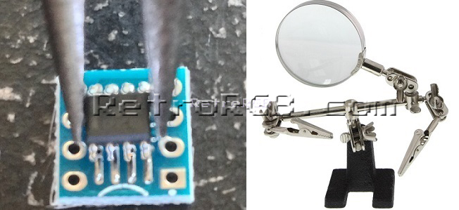
- Solder the THS7314 to the circuit board, but note the alignment of the vertical line on the chip and the square ground pin of the circuit board (see the top pic)! Since you tinned both the pads and pins, you should be able to place the amp on top of the circuit board and just touch the points with the tip of the soldering gun. This can be tricky, so it's recommended to use pliers, tweezers, or "helping hands" to hold the amp and circuit board.
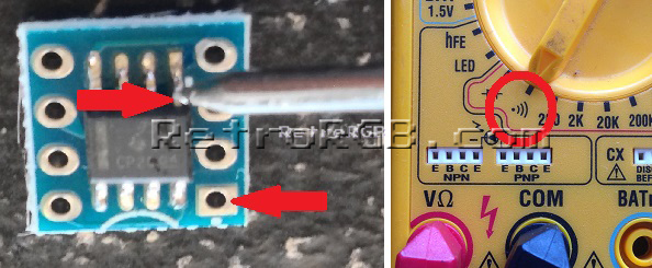
- Use a multimeter to check your solder points. When checking, make sure to touch the pin where it enters the chip, not near the bottom where you may accidentally be making contact with the circuit board's pads. Then, touch the other tester to the pad that matches it's input (ground shown here). If a connection isn't made, you could try adding more solder to the joint between the pad and pin:
You can use this diagram to test each of the pins and pads to make sure they line up. You'll want them to match the photo at the top of this page: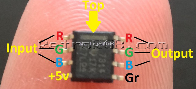
- Add the output resistors. Bend the resistor so it's close to the board and solder the top. Snip off the excess as short as possible (so the bottom of the circuit board is smooth) and add a bit more solder to the bottom:
- Add the capacitor between power and ground. In this installation, the capacitor acts as a "power filter", ensuring that the voltage running through doesn't cause interference with the signal. It may be easier to add the power and ground wires at the same time you add the capacitor, but it's not necessary:
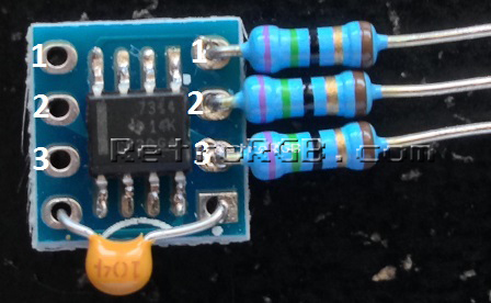


The inputs on the left will pass directly through to the inputs on the right (numbered as 1-3 in the above picture). You can use this amp to amplify pretty much any 3-channel SD video signal and even use it to amplify sync if needed (but you'd obviously only use one input/output if you were making a sync amp).
Brightness Levels / Attenuation
In some cases, this circuit will look perfect without any other components (like with the N64), but in many other cases, the image will be slightly too bright. In these scenarios, the best solution is to use an oscilloscope to measure the exact output and use a set of pulldown resistors. For SNES Mini and 1CHIP, these values are already calculated and shown in their respective guides.
THS7374
There's a newer, 4-channel revision of the chip called the 7374. The chip also includes an additional noise filter, which can be toggled off and on. It's recommended for this filter be turned off (tie pin 9 to 5v datasheet) for reasons mentioned above. Also, please keep in mind that this chip is MUCH smaller and almost impossible to solder by hand. As a result, it's not a good DIY solution, but great for surface-mount boards: 
How do they compare?
When going directly into a capture card that doesn't use a filter, all three are very close to the same. When run through a typical analog to digital filter, you start to see the sharpness differences with each. Here's all three, with the filter on the THS7374 turned off (click for an enlarged version): 