Master System:Model 1 SMS SMSFM Installation
The SMSFM board was primarily designed for installation in an original model Master System, and is therefore the easiest console to install it in. The general procedure for adding an SMSFM is largely the same on all model 1 revisions, with only the solder points for the audio wires differing.
This guide also applies to the Brazilian Master System/Master System II and the Korean Gam-Boy.
Materials and Tools
Materials
- SMSFM board
- Leaded solder
- Flux (not required but recommended)
- Hookup wire (optional depending on install)
Tools
- JIS/Phillips head screwdriver
- Soldering iron
- Desoldering braid or desoldering gun
- Flush cutters (optional)
- Wire stripper (optional)
- Drill with step bits (optional)
Procedure
- Flip over the Master System and remove the six JIS screws securing the case. Remove the top shell and set it aside.
- Most Master Systems will have RF shielding covering the motherboard, remove it and undo the remaining screws securing the motherboard. Set the bottom shell aside.
- Remove the heat sink for the 7805 voltage regulator. This may pose some difficulty on early board revisions as the 7805 is mounted inwards and is screwed into a very large heat sink.
- Begin assembling the SMSFM by soldering in the 50-pin connector. The components on the SMSFM need to be facing towards the front of the SMS, and needs to be soldered in at an angle so that the top of the SMSFM is tilted towards the front. If you do not tilt the SMSFM, it will not fit inside the top case.
- See Figure 1.
- Solder the pin header for the FM enable/disable/region switch onto the SMSFM, then solder the supplied wire harness to the switch.
- With the SMSFM board assembled, connect it to the expansion port at the rear of the SMS motherboard. Note that if you are keeping the top RF shield, you will need to either bend or cut the prongs that protrude from the shielding towards the expansion port, otherwise the SMSFM will not fit.
- See Figure 2.
- Be extremely careful cutting the RF shield as it will be very sharp. If desired, the cut edge can be dulled using sandpaper or a rotary tool.
- For the final installation step, the audio cable from the SMSFM needs to be soldered into the SMS motherboard. The white wire carries the standard PSG audio, where it will be mixed into the SMSFM. The final output including FM audio then goes out from the red wire. In addition, the cable on the SMSFM has an extra shield ground to reduce interference, which needs to be soldered to a ground source on the SMS. Soldering these wires will vary depending on the motherboard revision; follow the subsections below according to your specific console.
- For the switch, it can be placed inside the expansion port cover with the wire harness bunched up for a no-cut mod. If you want the switch to be easily accessible, a hole can be drilled on the rear of the top case or the RF modulator can be desoldered, which will leave a decent size hole for the switch without drilling into the case. Note that you may need to fit a washer behind the switch if you decide to fit the switch in the RF output hole. Connect the switch to the SMSFM once it is mounted.
- Place the motherboard back into the bottom shell and test. If you did not reattach the heat sink for the 7805, only test long enough to verify that the mod is working as the 7805 will overheat very quickly and shut down without a heat sink.
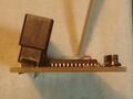
Fig. 1 - A side profile of an assembled SMSFM showing the tilt needed for it to fit inside a model 1.
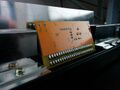
Fig. 2 - An installed SMSFM, note how the prongs on the RF shield have been removed.


Procedure for Audio Points
837-6067
This is the original board revision for the NTSC SMS. It is denoted by the use of metal leaf switches for Pause and Reset and a massive heat sink for the voltage regulator.
- Desolder or cut out capacitor C49, which is located below the RF modulator.
- Connect the white wire to the positive lead for C49 and the red wire to the negative. The ground wire can be soldered to the RF modulator casing or a nearby ground plane.

837-6097
This is the original board revision for the PAL SMS and also uses metal leaf switches.
- Desolder or cut out capacitor C48, which is located below the RF modulator.
- Connect the white wire to the positive lead for C49 and the red wire to the negative. The ground wire can be soldered to the RF modulator casing or a nearby ground plane.

837-6405, 837-6629 and 837-6700
These three revisions share much of the same layout and make up the majority of NTSC Master Systems. The latter two revisions were also used in France, albeit without a video encoder and other support circuitry. Installing the audio wires is a slightly different process on these particular consoles.
- Desolder capacitor C37, located near the CXA1145 video encoder chip.
- For French consoles, remove the wire connecting the positive lead of C37 to pin 9 of the CXA1145.
- Insert the white wire into the via for the positive lead, and the red wire for the negative lead (pin 9 of the CXA1145 for French consoles). The ground wire can be soldered to the RF modulator casing or a nearby ground plane.

VA1 and VA2
- Desolder or cut out capacitor C51, located between the RF modulator and CXA1145 encoder.
- Connect the white wire to the positive lead for C51 and the red wire to the negative. The ground wire can be soldered to the RF modulator casing or a nearby ground plane.
VA3
This PAL-only board revision uses the 315-5246 VDP and 315-5237 I/O chip like the Master System II. The polarity for the audio capacitor on this revision is reversed compared to all others.
- Desolder or cut out capacitor C62, located near the CXA1145 encoder and the VDP.
- Connect the white wire to the negative lead for C62 and the red wire to the positive. The ground wire can be soldered to the RF modulator casing or a nearby ground plane.

Samsung Gam-Boy
The Korean version of the model 1 Master System. It is largely based on the Japanese Master System and includes most of its extra features except for FM audio. It is possible to mod this console with the SMSFM, though it is not currently known if the region switching function works. In any case, it should be possible to install it the same way as other model 1s.
- Desolder or cut out the capacitor connected to pin 8 of the CXA1145 encoder.
- Connect the white wire to the positive lead for the audio capacitor and the red wire to the negative. The ground wire can be soldered to a nearby ground source.
TecToy Master System and Master System II
Audio from the SMSFM can be installed in two different ways on these models, depending on if you want FM audio through both RF and AV out, or just AV out.
- If FM audio through RF is desired, some trace cutting will be required. Flip over the motherboard and cut the trace going from pin 10 (PSG output) of the 315-5124 VDP to a nearby via. Solder the white wire directly onto pin 10 of the VDP and the red wire onto the via which was previously connected to pin 10. The ground wire can be soldered to a nearby ground source.
- If AV out is only used, desolder or cut out capacitor C45. Connect the white wire to the positive lead for C45 and the red wire to the negative. The ground wire can be soldered to a nearby ground source.

