Odyssey:Magnavox Odyssey Antenna-Game Switch: Difference between revisions
(Created page with "The Antenna-Game Switch is a mechanical TV RF switch box, similar to models produced for a range of first and second generation consoles. Its purpose was to allow the user to select either the Odyssey or regular television viewings, without having to disturb their antenna connections. 200px ==Operation== The rifle has a light sensor built in that responds when the barrel is lined up with a white light source, such as the square dot...") |
No edit summary |
||
| Line 5: | Line 5: | ||
==Operation== | ==Operation== | ||
The | The Game-Switch is connected to the main Odyssey console unit using the proprietary Game Cord. One end of the Game Cord is plugged into the Game Cord socket on the console, which the other end is plugged into the socket on the top of the Antenna-Game Switch marked Game Cord. | ||
To output the console's video signal to the television, the Antenna-Game Switch has an output cable that feeds into two fork connectors. These fork connectors would connect to screw-style VHF 300 Terminals on the back of the television. | |||
==Repairs== | |||
The most common damage to the Antenna-Game Switch is caused by rust, as the unit is made of metal. Additionally, the fork connectors are light and easily damaged. | |||
Fortunately, replacement fork terminals (also referred to as crimp spade connectors) are relatively easy to obtain, either uninsulated or insulated, [https://uk.rs-online.com/web/p/fork-terminals/2082521 as shown below]. | |||
The model of fork connectors shown below are "M3", which means that they will fit securely to an M3-sized screw. (Link > [https://www.fastenermart.com/understanding-metric-fasteners.html Detailed Explanation of Metric Fasteners]). | |||
[[File:Insulated M3 fork connectors .jpg|200px]] | |||
When selecting a fork connector, the user should also consider the gauge of the cable. | |||
The cables which need to be soldered to the fork connectors are approximately 3.13mm, and 1.56mm when the cable insulation is stripped back (see below). | |||
[[File:Switchbox cable 1.jpg|200px]] | |||
[[File:Switchbox cable 2.jpg|200px]] | |||
Additionally, the VHF Antenna connection on the bottom of the unit may become rusted and damaged over time. This can be replaced by a "Straight 75Ω RF Adapter Type F Socket to Type F Socket 1GHz". The replacement would need to be threaded through the hole in the bottom of the switch box, and may need to be soldered into place to remain securely. | |||
[[File:Rf adapters for Odyssey switch box.jpg|200px]] | |||
== Links == | == Links == | ||
* [https:// | * [https://uk.rs-online.com/web/p/fork-terminals/2082521/(RS PRO Insulated Crimp Spade Connector, 1.5mm² to 2.5mm², 16AWG to 14AWG, 3.2mm Stud Size Vinyl, Blue) ] | ||
* [https:// | * [https://uk.rs-online.com/web/p/coaxial-adapters/5462728 Straight 75Ω RF Adapter Type F Socket to Type F Socket 1GHz] | ||
[[Category:Magnavox Odyssey]] | [[Category:Magnavox Odyssey]] | ||
Revision as of 14:02, 28 April 2022
The Antenna-Game Switch is a mechanical TV RF switch box, similar to models produced for a range of first and second generation consoles. Its purpose was to allow the user to select either the Odyssey or regular television viewings, without having to disturb their antenna connections.
Operation
The Game-Switch is connected to the main Odyssey console unit using the proprietary Game Cord. One end of the Game Cord is plugged into the Game Cord socket on the console, which the other end is plugged into the socket on the top of the Antenna-Game Switch marked Game Cord.
To output the console's video signal to the television, the Antenna-Game Switch has an output cable that feeds into two fork connectors. These fork connectors would connect to screw-style VHF 300 Terminals on the back of the television.
Repairs
The most common damage to the Antenna-Game Switch is caused by rust, as the unit is made of metal. Additionally, the fork connectors are light and easily damaged.
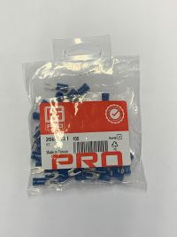
Fortunately, replacement fork terminals (also referred to as crimp spade connectors) are relatively easy to obtain, either uninsulated or insulated, as shown below.
The model of fork connectors shown below are "M3", which means that they will fit securely to an M3-sized screw. (Link > Detailed Explanation of Metric Fasteners).
When selecting a fork connector, the user should also consider the gauge of the cable.
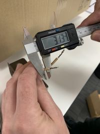
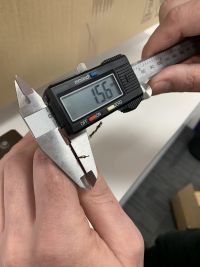
The cables which need to be soldered to the fork connectors are approximately 3.13mm, and 1.56mm when the cable insulation is stripped back (see below).
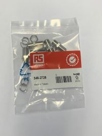
Additionally, the VHF Antenna connection on the bottom of the unit may become rusted and damaged over time. This can be replaced by a "Straight 75Ω RF Adapter Type F Socket to Type F Socket 1GHz". The replacement would need to be threaded through the hole in the bottom of the switch box, and may need to be soldered into place to remain securely.


