SNES:SNES Jr DIY S-RGB Mod: Difference between revisions
Jump to navigation
Jump to search
No edit summary |
No edit summary |
||
| Line 5: | Line 5: | ||
Modding Services: | === Modding Services: === | ||
: [http://store.retrofixes.com Retrofixes SNES Mini RGB Mod - USA] | : [http://store.retrofixes.com Retrofixes SNES Mini RGB Mod - USA] | ||
| Line 12: | Line 12: | ||
Parts required: | === Parts required: === | ||
: You'll need a few tools for this mod (more info on the tools can be found in [tools.html the tools section]): | : You'll need a few tools for this mod (more info on the tools can be found in [tools.html the tools section]): | ||
| Line 27: | Line 27: | ||
: [http://www.mouser.com/ProductDetail/KOA-Speer/MF1-4DCT52R1201F http://www.mouser.com/ProductDetail/KOA-Speer/MF1-4DCT52R1201F] | : [http://www.mouser.com/ProductDetail/KOA-Speer/MF1-4DCT52R1201F http://www.mouser.com/ProductDetail/KOA-Speer/MF1-4DCT52R1201F] | ||
RGB Mod: | === RGB Mod: === | ||
The mod is pretty easy, however soldering to the S-RGB chip can be extremely challenging. Its usually recommended people use a pre-made amp for ease of installation, however if you're willing to solder to the small points this will work perfectly: | The mod is pretty easy, however soldering to the S-RGB chip can be extremely challenging. Its usually recommended people use a pre-made amp for ease of installation, however if you're willing to solder to the small points this will work perfectly: | ||
| Line 48: | Line 48: | ||
: [[File:SNESMiniRGBModPage06.jpg]] | : [[File:SNESMiniRGBModPage06.jpg]] | ||
Results: | === Results: === | ||
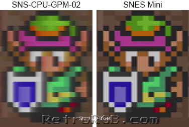
: That’s it! A pretty easy mod and the picture quality is amazing!!! Check out the difference from an average SNES 1 to a SNES Mini: | : That’s it! A pretty easy mod and the picture quality is amazing!!! Check out the difference from an average SNES 1 to a SNES Mini: | ||
: [[File:SNS-CPU-GPM-02vsSNESMini.png]] | : [[File:SNS-CPU-GPM-02vsSNESMini.png]] | ||
Revision as of 22:38, 12 June 2022
Mitch1256
SNES Mini RGB Mod - Onboard S-RGB Amp
This guide shows you how to enable RGB output on a SNES Mini / Jr using its built-in RGB amp. If you'd like this mod performed for you, you can hire the following services:
Modding Services:
Parts required:
- You'll need a few tools for this mod (more info on the tools can be found in [tools.html the tools section]):
- Soldering skills!
- SNES RGB cable
- The 4.5mm tool that opens the SNES
- Philips head screwdriver
- Soldering iron / solder
- Thin gauge wire
- Flux (or a flux pen) will make installation easier, but is not necessary.
- Three 75 Ohm resistors, the lowest tolerance possible (also available from Digikey):
- http://www.mouser.com/ProductDetail/Vishay/MRS25000C7509FRP00
- Three 1.2k resistors, the lowest tolerance possible (not available from Digikey):
- http://www.mouser.com/ProductDetail/KOA-Speer/MF1-4DCT52R1201F
RGB Mod:
The mod is pretty easy, however soldering to the S-RGB chip can be extremely challenging. Its usually recommended people use a pre-made amp for ease of installation, however if you're willing to solder to the small points this will work perfectly:
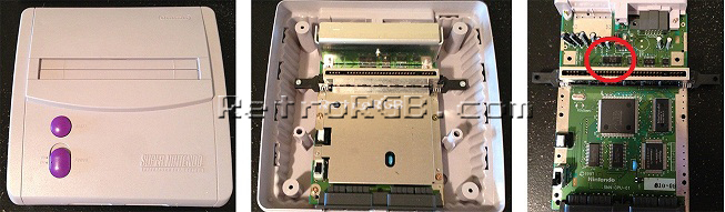
- Remove the 4 screws holding the plastic cover on using the 4.5mm tool. Then remove the 7 screws holding the motherboard in place (so, basically, just unbolt everything). Finally, unbolt the three screws holding the heatsink and find the S-RGB chip:
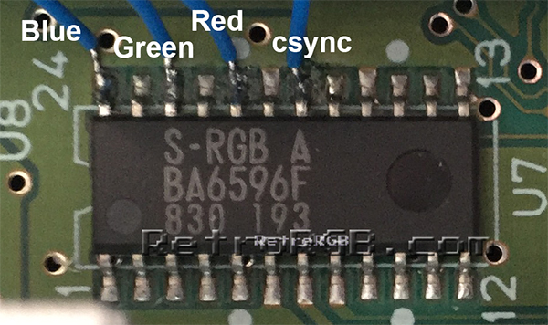
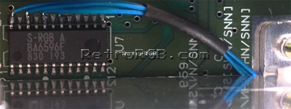
- Solder four wires to the pins on the “S-RGB A” chip shown below. A few tips: These are extremely small pins and very difficult for people who aren't experienced at soldering to work on. Use a soldering tip that's extremely thin, as well as very thin solder. Make sure to "tin" each pin and each wire before trying to solder them together:
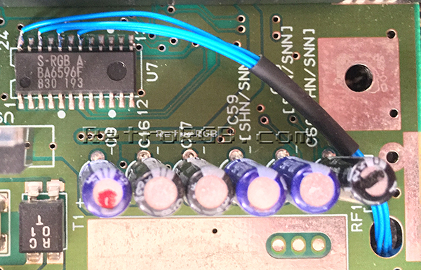
- It's recommended to use heatshrink tubing to keep the wires together and also protect them from touching any other components. Then, run the cables through the hole pictured below on the right:
- Then, carefully replace the heatsink. Run the wires under the heatsink, since there's enough room; They touch, but aren't being crushed:
- Cut the wires to size, add the 75 Ohm resistors to the RGB lines, then solder them to the corresponding pins on the multi-out.
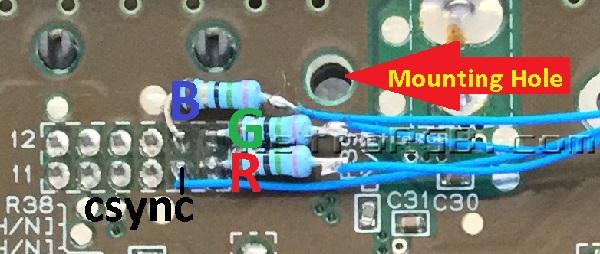
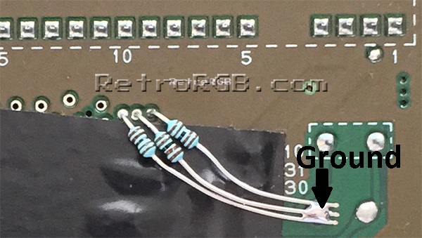
- Next you need to add resistors to the RGB inputs that adjust the brightness. The mod will work without these resistors, but it's recommended you add them (and it's really easy). Simply solder three 1.2k resistors between the three holes located directly under pin 10 of the cartridge port and a ground point (flux is a big help for this). The picture below shows non-conductive tape covering the components under the resistor, however using heatshrink tubing is a better solution overall. AFTER YOU'RE DONE SOLDERING, FLIP THE MOTHERBOARD OVER AND MAKE SURE TO TRIM THE EXTRA LENGTH!!!! It's very common to have these touch something on the other side, so make sure you check the length! Click the picture below for a full-sized example:


Results:
- That’s it! A pretty easy mod and the picture quality is amazing!!! Check out the difference from an average SNES 1 to a SNES Mini: