Atari 5200:Connector Pinouts: Difference between revisions
Jump to navigation
Jump to search
(Created page with "==Cartridge Port== ==Controller Port== <small>Note: Female is connector at the console. Male is connector at the controller. Diagram pictured is of the connector at the controller end.</small> File:5200controller.png {| class="wikitable" |- ! Pin # !! Description !! Wire Color |- | 1 || Column Data (Right Keypad Column) || Gray |- | 2 || Column Data (Middle Keypad Column) || White |- | 3 || Column Data (Left Keypad Column) || Orange |- | 4 || Auxiliary Keypad Col...") |
No edit summary |
||
| Line 1: | Line 1: | ||
==Cartridge Port== | ==Cartridge Port== | ||
==Controller Port== | ==Controller Port== | ||
| Line 43: | Line 42: | ||
==Expansion Port== | ==Expansion Port== | ||
<small>Note: Pins 1 through 18 are at the top and numbered from left to right. Pins 19 through 36 are at the bottom and numbered from right to left.</small> | |||
{| class="wikitable" | |||
! Pin # !! Description | |||
|- | |||
| 1 || 5V (VCC) | |||
|- | |||
| 2 || Not Connected (4-port) / Audio Out (2-port) | |||
|- | |||
| 3 || Ground | |||
|- | |||
| 4 || WE (Write Enable) | |||
|- | |||
| 5 || CS0 | |||
|- | |||
| 6 || D6 | |||
|- | |||
| 7 || D4 | |||
|- | |||
| 8 || D2 | |||
|- | |||
| 9 || D0 | |||
|- | |||
| 10 || IRQ | |||
|- | |||
| 11 || Ground | |||
|- | |||
| 12 || Data In | |||
|- | |||
| 13 || Clock In | |||
|- | |||
| 14 || Clock Out | |||
|- | |||
| 15 || Data Out | |||
|- | |||
| 16 || Audio Input | |||
|- | |||
| 17 || A14 | |||
|- | |||
| 18 || System Clock | |||
|- | |||
| 19 || A11 | |||
|- | |||
| 20 || A7 | |||
|- | |||
| 21 || A6 | |||
|- | |||
| 22 || A5 | |||
|- | |||
| 23 || A4 | |||
|- | |||
| 24 || A3 | |||
|- | |||
| 25 || A2 | |||
|- | |||
| 26 || A1 | |||
|- | |||
| 27 || A0 | |||
|- | |||
| 28 || Ground | |||
|- | |||
| 29 || D1 | |||
|- | |||
| 30 || D3 | |||
|- | |||
| 31 || D5 | |||
|- | |||
| 32 || D7 | |||
|- | |||
| 33 || Not Connected | |||
|- | |||
| 34 || Ground | |||
|- | |||
| 35 || Not Connected | |||
|- | |||
| 36 || 5V (VCC) | |||
|} | |||
Revision as of 06:47, 17 October 2022
Cartridge Port
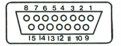
Controller Port
Note: Female is connector at the console. Male is connector at the controller. Diagram pictured is of the connector at the controller end.
| Pin # | Description | Wire Color |
|---|---|---|
| 1 | Column Data (Right Keypad Column) | Gray |
| 2 | Column Data (Middle Keypad Column) | White |
| 3 | Column Data (Left Keypad Column) | Orange |
| 4 | Auxiliary Keypad Column | Orange and White |
| 5 | Row Data (Keypad Row 3) | Blue |
| 6 | Row Data (Keypad Row 2) | Violet |
| 7 | Row Data (Keypad Row 1) | Red and White |
| 8 | Row Data (Keypad Row 4) | Green |
| 9 | Potentiometer Voltage (+CAV) | Black |
| 10 | Potentiometer X Axis | Brown |
| 11 | Potentiometer Y Axis | Red |
| 12 | Unused | N/A |
| 13 | Bottom Fire Button | Yellow |
| 14 | Top Fire Button | Green and White |
| 15 | Ground | Orange |
Expansion Port
Note: Pins 1 through 18 are at the top and numbered from left to right. Pins 19 through 36 are at the bottom and numbered from right to left.
| Pin # | Description |
|---|---|
| 1 | 5V (VCC) |
| 2 | Not Connected (4-port) / Audio Out (2-port) |
| 3 | Ground |
| 4 | WE (Write Enable) |
| 5 | CS0 |
| 6 | D6 |
| 7 | D4 |
| 8 | D2 |
| 9 | D0 |
| 10 | IRQ |
| 11 | Ground |
| 12 | Data In |
| 13 | Clock In |
| 14 | Clock Out |
| 15 | Data Out |
| 16 | Audio Input |
| 17 | A14 |
| 18 | System Clock |
| 19 | A11 |
| 20 | A7 |
| 21 | A6 |
| 22 | A5 |
| 23 | A4 |
| 24 | A3 |
| 25 | A2 |
| 26 | A1 |
| 27 | A0 |
| 28 | Ground |
| 29 | D1 |
| 30 | D3 |
| 31 | D5 |
| 32 | D7 |
| 33 | Not Connected |
| 34 | Ground |
| 35 | Not Connected |
| 36 | 5V (VCC) |
