Genesis:Connector Pinouts: Difference between revisions
| Line 56: | Line 56: | ||
==Cartridge Port== | ==Cartridge Port== | ||
<small>Note: The "A" row is towards the back and numbered from left to right. The "B" row pins are towards the front and also numbered from left to right. This table is oriented so the front of the port is facing left.</small> | |||
{| class="wikitable" | |||
|+ | |||
!Pin # | |||
!Description | |||
!Pin # | |||
!Description | |||
|- | |||
|'''B1''' | |||
|SL1 (External Left Audio) / Unused on Genesis 3 | |||
|'''A1''' | |||
|Ground | |||
|- | |||
|'''B2''' | |||
|/MRES | |||
|'''A2''' | |||
|5V | |||
|- | |||
|'''B3''' | |||
|SR1 (External Right Audio) / Unused on Genesis 3 | |||
|'''A3''' | |||
|VA8 | |||
|- | |||
|'''B4''' | |||
|VA9 | |||
|'''A4''' | |||
|VA11 | |||
|- | |||
|'''B5''' | |||
|VA10 | |||
|'''A5''' | |||
|VA7 | |||
|- | |||
|'''B6''' | |||
|VA18 | |||
|'''A6''' | |||
|VA12 | |||
|- | |||
|'''B7''' | |||
|VA19 | |||
|'''A7''' | |||
|VA6 | |||
|- | |||
|'''B8''' | |||
|VA20 | |||
|'''A8''' | |||
|VA13 | |||
|- | |||
|'''B9''' | |||
|VA21 | |||
|'''A9''' | |||
|VA5 | |||
|- | |||
|'''B10''' | |||
|VA22 | |||
|'''A10''' | |||
|VA14 | |||
|- | |||
|'''B11''' | |||
|VA23 | |||
|'''A11''' | |||
|VA4 | |||
|- | |||
|'''B12''' | |||
|YS (Blanking) / Unused on Genesis 3 | |||
|'''A12''' | |||
|VA15 | |||
|- | |||
|'''B13''' | |||
|VSYNC (Vertical Sync) / Unused on Genesis 3 | |||
|'''A13''' | |||
|VA3 | |||
|- | |||
|'''B14''' | |||
|HSYNC (Horizontal Sync) / Unused on Genesis 3 | |||
|'''A14''' | |||
|VA16 | |||
|- | |||
|'''B15''' | |||
|EDCLK / Unused on Genesis 3 | |||
|'''A15''' | |||
|VA2 | |||
|- | |||
|'''B16''' | |||
|/CAS0 | |||
|'''A16''' | |||
|VA17 | |||
|- | |||
|'''B17''' | |||
|/CE_0 (Cartridge Enable) | |||
|'''A17''' | |||
|VA1 | |||
|- | |||
|'''B18''' | |||
|/AS (Address Strobe) | |||
|'''A18''' | |||
|Ground | |||
|- | |||
|'''B19''' | |||
|VCLK / Unused on Genesis 3 | |||
|'''A19''' | |||
|VD7 | |||
|- | |||
|'''B20''' | |||
|/DTACK (Data Transfer Acknowledge) | |||
|'''A20''' | |||
|VD0 | |||
|- | |||
|'''B21''' | |||
|/CAS2 / Unused on Genesis 3 | |||
|'''A21''' | |||
|VD8 | |||
|- | |||
|'''B22''' | |||
|VD15 | |||
|'''A22''' | |||
|VD6 | |||
|- | |||
|'''B23''' | |||
|VD14 | |||
|'''A23''' | |||
|VD1 | |||
|- | |||
|'''B24''' | |||
|VD13 | |||
|'''A24''' | |||
|VD9 | |||
|- | |||
|'''B25''' | |||
|VD12 | |||
|'''A25''' | |||
|VD5 | |||
|- | |||
|'''B26''' | |||
|/ASEL | |||
|'''A26''' | |||
|VD2 | |||
|- | |||
|'''B27''' | |||
|/VRES (68000 Reset) | |||
|'''A27''' | |||
|VD10 | |||
|- | |||
|'''B28''' | |||
|/LWR | |||
|'''A28''' | |||
|VD4 | |||
|- | |||
|'''B29''' | |||
|/UWR | |||
|'''A29''' | |||
|VD3 | |||
|- | |||
|'''B30''' | |||
|/M3 (Master System enable, must be held low to activate) / Unused on Genesis 3 | |||
|'''A30''' | |||
|VD11 | |||
|- | |||
|'''B31''' | |||
|/TIME | |||
|'''A31''' | |||
|5V | |||
|- | |||
|'''B32''' | |||
|/CART / Unused on Genesis 3 | |||
|'''A32''' | |||
|Ground | |||
|} | |||
==Controller Port== | ==Controller Port== | ||
Revision as of 18:32, 11 February 2023
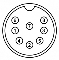
AV Out (Model 1)
Note: Connector is the female end at the console.
| Pin # | Description |
|---|---|
| 1 | Composite Video Out / Unused (French Mega Drive) |
| 2 | Ground |
| 3 | Audio Out |
| 4 | Green |
| 5 | 5V |
| 6 | Composite Sync |
| 7 | Red |
| 8 | Blue |
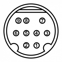
AV Out (Model 2 and 3)
This connector is also used in the Genesis Nomad, Mega Jet, 32X, CDX, and most X'Eye consoles. Ground is at the cable shroud.
Note: Connector is the female end at the console.
| Pin # | Description |
|---|---|
| 1 | Blue |
| 2 | 5V |
| 3 | Green |
| 4 | Composite Video |
| 5 | Composite Sync |
| 6 | Mono Audio |
| 7 | Red |
| 8 | Left Audio / Mono Audio (Genesis 3) |
| 9 | Right Audio / Unused (Genesis 3) |
Cartridge Port
Note: The "A" row is towards the back and numbered from left to right. The "B" row pins are towards the front and also numbered from left to right. This table is oriented so the front of the port is facing left.
| Pin # | Description | Pin # | Description |
|---|---|---|---|
| B1 | SL1 (External Left Audio) / Unused on Genesis 3 | A1 | Ground |
| B2 | /MRES | A2 | 5V |
| B3 | SR1 (External Right Audio) / Unused on Genesis 3 | A3 | VA8 |
| B4 | VA9 | A4 | VA11 |
| B5 | VA10 | A5 | VA7 |
| B6 | VA18 | A6 | VA12 |
| B7 | VA19 | A7 | VA6 |
| B8 | VA20 | A8 | VA13 |
| B9 | VA21 | A9 | VA5 |
| B10 | VA22 | A10 | VA14 |
| B11 | VA23 | A11 | VA4 |
| B12 | YS (Blanking) / Unused on Genesis 3 | A12 | VA15 |
| B13 | VSYNC (Vertical Sync) / Unused on Genesis 3 | A13 | VA3 |
| B14 | HSYNC (Horizontal Sync) / Unused on Genesis 3 | A14 | VA16 |
| B15 | EDCLK / Unused on Genesis 3 | A15 | VA2 |
| B16 | /CAS0 | A16 | VA17 |
| B17 | /CE_0 (Cartridge Enable) | A17 | VA1 |
| B18 | /AS (Address Strobe) | A18 | Ground |
| B19 | VCLK / Unused on Genesis 3 | A19 | VD7 |
| B20 | /DTACK (Data Transfer Acknowledge) | A20 | VD0 |
| B21 | /CAS2 / Unused on Genesis 3 | A21 | VD8 |
| B22 | VD15 | A22 | VD6 |
| B23 | VD14 | A23 | VD1 |
| B24 | VD13 | A24 | VD9 |
| B25 | VD12 | A25 | VD5 |
| B26 | /ASEL | A26 | VD2 |
| B27 | /VRES (68000 Reset) | A27 | VD10 |
| B28 | /LWR | A28 | VD4 |
| B29 | /UWR | A29 | VD3 |
| B30 | /M3 (Master System enable, must be held low to activate) / Unused on Genesis 3 | A30 | VD11 |
| B31 | /TIME | A31 | 5V |
| B32 | /CART / Unused on Genesis 3 | A32 | Ground |
Controller Port
Note: Female is connector at the console. Male is connector at the controller. Diagram pictured is of the connector at the controller end.
| Pin # | Description |
|---|---|
| 1 | Up/Button Z |
| 2 | Down/Button Y |
| 3 | Left/Ground/Button X |
| 4 | Right/Ground/Mode |
| 5 | 5V |
| 6 | Button B/A |
| 7 | Multiplexer Select |
| 8 | Ground |
| 9 | Button C/Start |
Expansion Port
EXT Port
This connector is only found on older model 1 consoles, all model 1 Japanese Mega Drive consoles, the TeraDrive and Wondermega. It is located at the rear of these consoles, and is essentially identical to the controller ports, though is typically used to send serial data to the VDP instead of being used as an extra controller port. The most notable accessory to use this connector is the Mega Modem, which was only released in Japan.
Note: Diagram pictured is of the connector at the console end.
| Pin # | Description |
|---|---|
| 1 | Up |
| 2 | Down |
| 3 | Left/Ground |
| 4 | Right/Ground |
| 5 | 5V |
| 6 | Button B/A |
| 7 | Multiplexer Select |
| 8 | Ground |
| 9 | Button C/Start |


