Jaguar:Video Output Notes: Difference between revisions
Jump to navigation
Jump to search
(From retrorgb) |
mNo edit summary |
||
| Line 1: | Line 1: | ||
== RGB == | |||
The Atari Jaguar will output RGB natively and only an RGB cable is needed. You can make one yourself, but some sellers are listed below. | The Atari Jaguar will output RGB natively and only an RGB cable is needed. You can make one yourself, but some sellers are listed below. | ||
===Sellers=== | |||
* [https://retro-access.com/collections/atari-jaguar-cables/products/atari-jaguar-rgb-scart-cable-with-dedicated-connector-hood?aff=3 Atari Jaguar RGB SCART cable (US Seller)] | * [https://retro-access.com/collections/atari-jaguar-cables/products/atari-jaguar-rgb-scart-cable-with-dedicated-connector-hood?aff=3 Atari Jaguar RGB SCART cable (US Seller)] | ||
== Video Port Pinout == | |||
The cable plug uses a [http://www.digikey.com/scripts/DkSearch/dksus.dll?WT.z_header=search_go&lang=en&keywords=S3304-ND&x=0&y=0&cur=USD 24-pin dual-edge connector] (.100 DIP). | |||
When making an RGB cable: | |||
* Wire RGB to pins 4B, 7A, 5A (respectively). | |||
* Wire RGB ground to pin 10B. | |||
* Wire CSYNC to pin 5B with a 680 ohm, 1/4 watt resistor and a 220uF/16v capacitor in series. | |||
* Make sure to not share video ground with audio ground. Audio ground will be tied to pin 2A. | |||
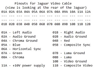
Here's a diagram from [http://www.atarimax.com/freenet/freenet_material/9.JaguarSupportArea/3.ReferenceDesk/31FrequentlyAskedQuestions.php Atarimax.com]: | |||
[[File:JaguarAVPinout.jpg]] | |||
Revision as of 21:40, 13 July 2023
RGB
The Atari Jaguar will output RGB natively and only an RGB cable is needed. You can make one yourself, but some sellers are listed below.
Sellers
Video Port Pinout
The cable plug uses a 24-pin dual-edge connector (.100 DIP).
When making an RGB cable:
- Wire RGB to pins 4B, 7A, 5A (respectively).
- Wire RGB ground to pin 10B.
- Wire CSYNC to pin 5B with a 680 ohm, 1/4 watt resistor and a 220uF/16v capacitor in series.
- Make sure to not share video ground with audio ground. Audio ground will be tied to pin 2A.
Here's a diagram from Atarimax.com:
