Genesis:Mega Nomad: Difference between revisions
No edit summary |
m (Text replacement - " : " to ": ") |
||
| Line 46: | Line 46: | ||
=== Installation === | === Installation === | ||
You should have soldering skills and be able to disassemble the console. The pictures below should be sufficient enough to have the console modified with MegaNomad board. You can also check this manual just for reference on how to open the console etc. : http://www.sega-16.com/forum/showthread.php?29563-How-to-region-mod-a-SEGA-Nomad-NTSC-JAPAN-ONLY-(Thunderblaze16) | You should have soldering skills and be able to disassemble the console. The pictures below should be sufficient enough to have the console modified with MegaNomad board. You can also check this manual just for reference on how to open the console etc.: http://www.sega-16.com/forum/showthread.php?29563-How-to-region-mod-a-SEGA-Nomad-NTSC-JAPAN-ONLY-(Thunderblaze16) | ||
The mod board looks like this on the back: | The mod board looks like this on the back: | ||
Revision as of 18:14, 12 August 2023
Introduction
The ultimate switchless mod for LCD modded Nomads! Based on the Sebastian Kienzl’s code.
Availability
- Creators website - https://vmod.wordpress.com/mega-nomad-v1-0/
- VideoGamePerfection.com - https://videogameperfection.com/products/mega-nomad-board/
Features
- Correct frequency carrier for PAL – No more black/white picture when in 50HZ (PAL). Precise frequency for quality PAL color picture.
- Switchless mod – change region / video modes via the Mode button.
- LED indicator – 3 color external LED shows the current mode (Green – EU, Red – JAP, Orange – US). It is placed additionally in the console.
- Works great with the TV out cable – play your games in PAL/NTSC or any region on your TV via the original cable! (your TV must support composite PAL/NTSC)
Mode Button
- Short press <250ms – normal console reset
- Long press between 250ms and 1250ms – 50/60 Hz on-the-fly switch (after button is released the LED flashes slow – 50Hz or fast – 60Hz)
- Hold for more than 1250ms – As long as the button is pressed, the regions are cycled through (1sec each). After the button is released the region-setting gets changed and the console will reset so the new region-settings take effect.
All settings are stored in the internal memory, so after console reset it will remain in the last set mode.
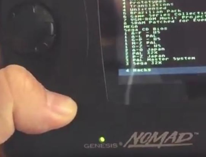
Here’s a demo of how this board works in a LCD modded Nomad: https://youtu.be/hcYoRYhMivg
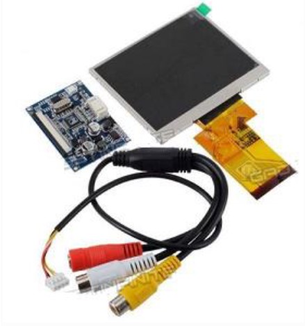
This LCD was recommended for the mod, it has a blue driver board PCB. You can find it in ebay, just use "3.5' LCD TFT rear camera monitor" etc. keywords. However, any replacement LCD should be compatible.
It's also good to have the LCD board modded to use 5V instead of 12V. It saves battery power! Here, under Method 2 https://nobitleftbehind.wordpress.com/2014/06/14/fix-for-lcd-replacement-mod-blinking/
Other LCD displays can be used, but you have to test them through the TV out before putting them in the console. Just mod the console with Mega Nomad and test the LCD externally with the original Sega composite TV cable. (the one with the yellow, red and white plugs)
Warning! Creator takes no responsibility if you mess this modification up. Do the mod at your own risk, or get someone more experienced to do it for you!
Kit contents:
- 1 x Mega Nomad v1.0 board
- 1 x 3 color LED
LCD display and LCD driver board are NOT INCLUDED in the kit!
Installation
You should have soldering skills and be able to disassemble the console. The pictures below should be sufficient enough to have the console modified with MegaNomad board. You can also check this manual just for reference on how to open the console etc.: http://www.sega-16.com/forum/showthread.php?29563-How-to-region-mod-a-SEGA-Nomad-NTSC-JAPAN-ONLY-(Thunderblaze16)
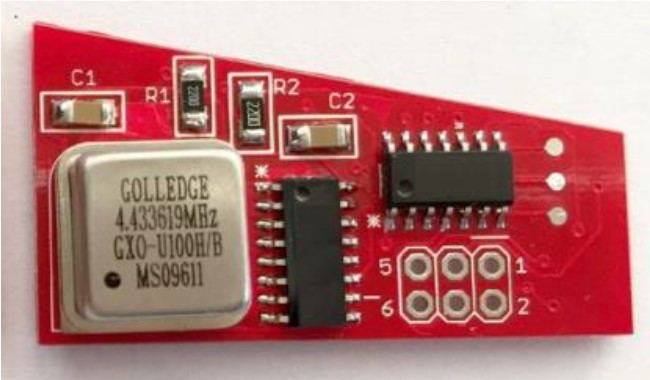
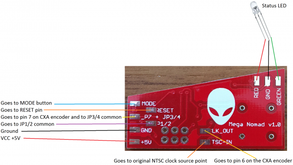
The mod board looks like this on the back:
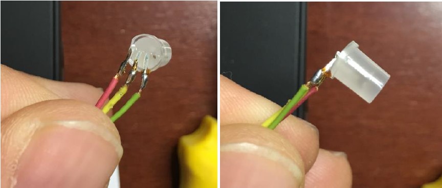
You can test the LED with a small 3v button battery to see which pin is red and which is green.
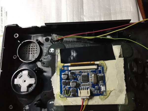
You must first install the new LCD screen and have it working before adding the mod board. Make sure it’s centered properly before gluing! It should look something like this:
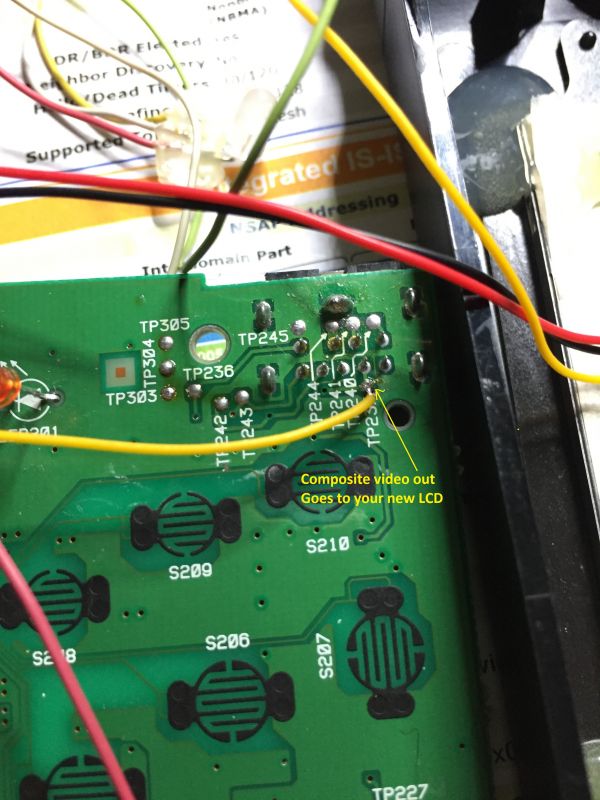
Take composite video signal from here if needed by your replacement screen:
Drill a small hole just above the E letter on the GENESIS label in front. This is for the status LED install.
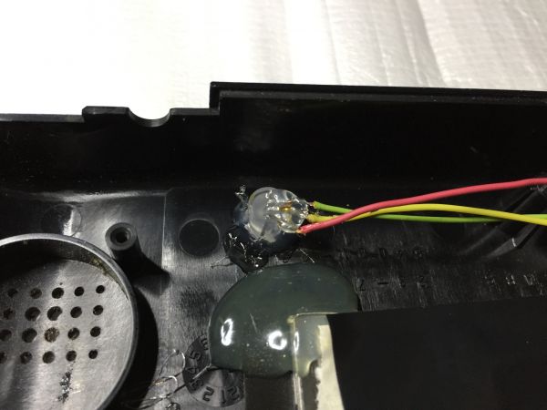
You can take some of the front material of the LED before you hot glue it so it would stay levelled and be easier for gluing. Solder the wires and hot glue it in place.
Solder the wires on the other end to the mod board LED pins.
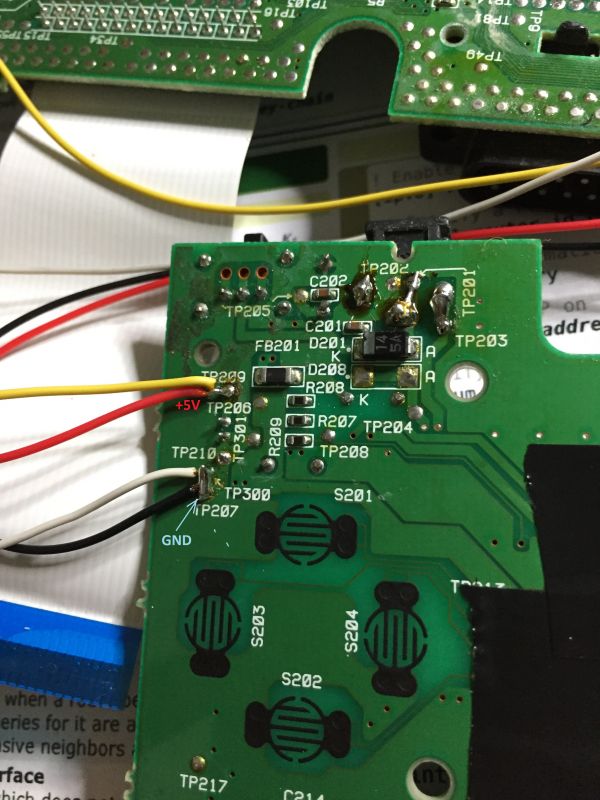
Next solder wires for 5V VCC and GND:
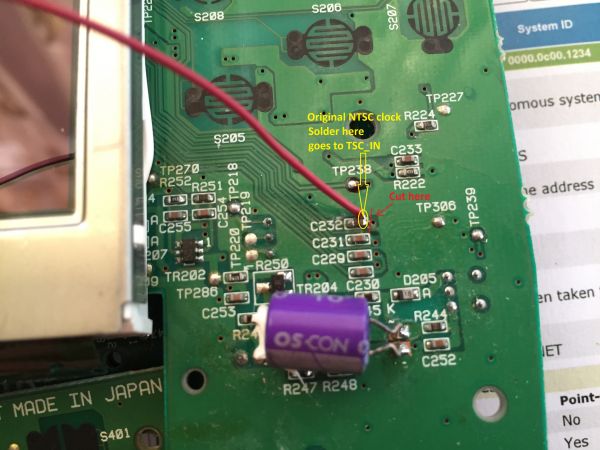
You have to make a small cut right next to C232 where the small via hole is. The trace should be cut between the C232 and the hole. This is necessary to have the original NTSC source clock isolated from the CXA encoder.
Solder a wire on the right side of C232, this wire will go to TSC_IN on the mod board. Be careful.
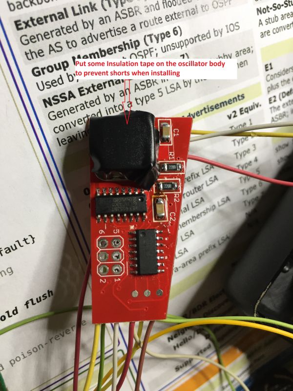
Place insulation tape on the mod board oscillator to prevent shorts when gluing:
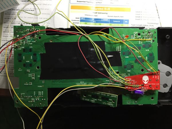
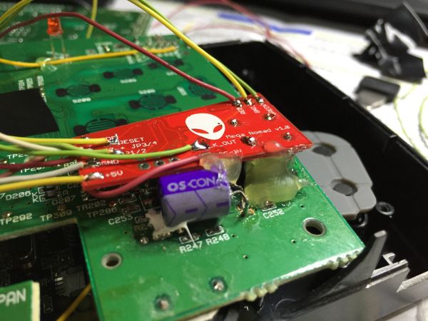
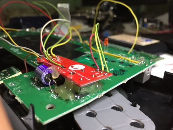
If you prefer you can hot glue the mod board to the main board now or do it later. I suggest doing it later. Place it exactly as shown on picture. It’s designed to fit just below the 6 buttons.
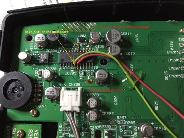
Next you have to flip the mainboard. You’ll find a Sony CXA encoder chip. You have to cut the trace going to pin 7 as shown on the picture. Solder two wires to pin6 and pin7 on the chip as shown. Pin 6 goes to LK_OUT and pin 7 goes to _P7 + JP3/4 on the mod board.
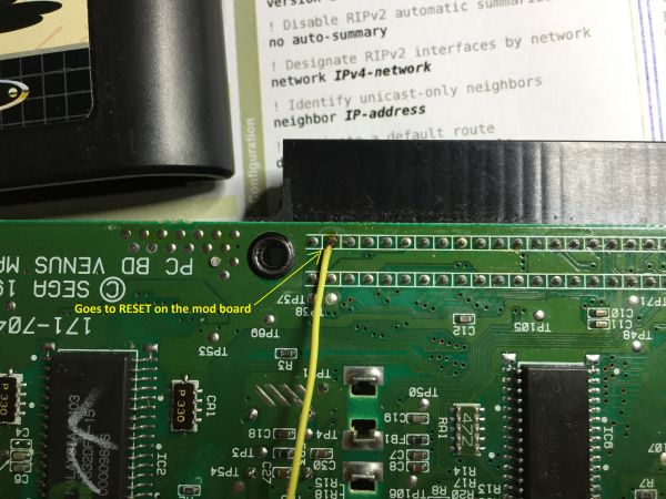
Next we go to the other mainboard of the console. Solder a wire to the RESET pin here:
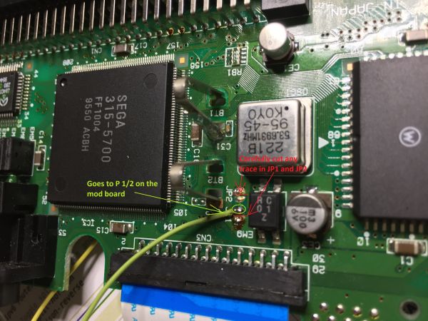
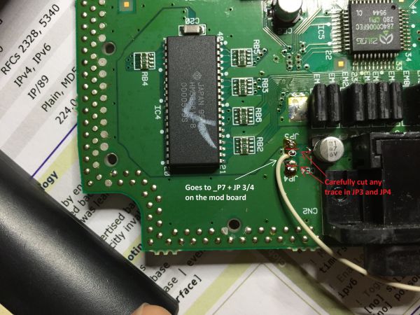
On the other side of the second mainboard you’ll find JP1/JP2 and JP3/JP4. Cut any traces between JP1/2 and JP3/4 as shown. Solder wires to the shown points, be careful not to short anything.
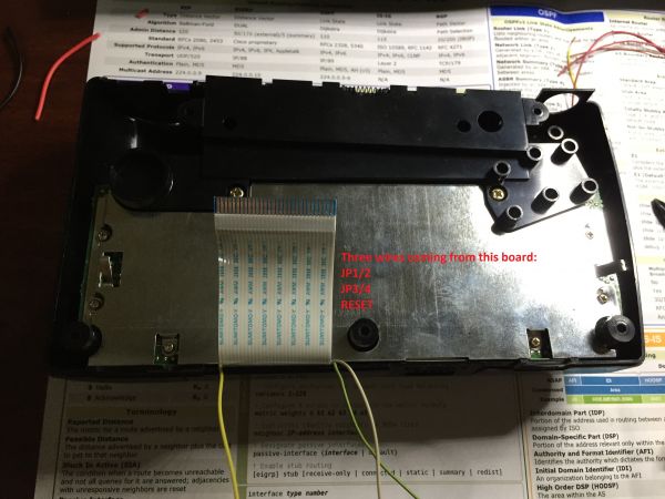
These jumpers are for controlling the region and 50/60HZ modes on the console. When you assemble the second mainboard with the plastic cover you should have 3 wires coming from it:
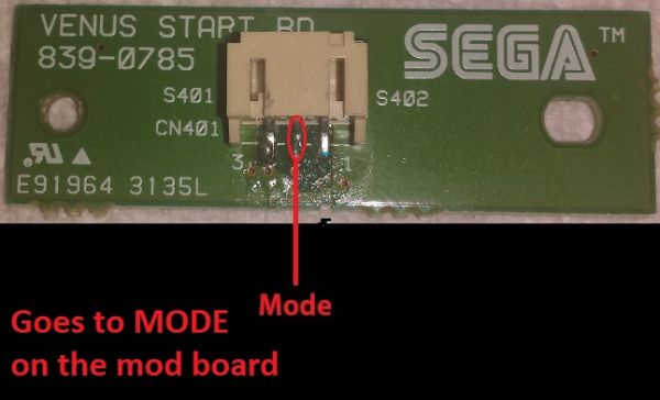
The last wire comes from the MODE button on the console. Mode and start buttons are on a separate PCB connected with a 3-wire jumper cable. Solder a wire to either end of the cable, to the middle pin (MODE).
This wire goes to MODE solder point on the mod board.
By now you should have all wires soldered to the mod board. Note that you have two wires going to the same solder point _P7 + JP3/4 on the mod board.
When you’re ready test everything before putting it back together. Make sure that every feature works as expected.
Finally, enjoy your new upgraded Nomad!
