Backlight Mod
m (Derf moved page Backlight Mod to Backlight Mod) |
No edit summary |
||
| Line 73: | Line 73: | ||
# Pop the LCD frame back onto the LCD board and flux the solder pads. Place the horizontal cable roughly in the right place, and screw the Horizontal set screw partially in, but not all the way. Tack the pins in with your iron, using the bevel of the iron tip. Screw the set screw in all the way, and reflow the solder on the pins. | # Pop the LCD frame back onto the LCD board and flux the solder pads. Place the horizontal cable roughly in the right place, and screw the Horizontal set screw partially in, but not all the way. Tack the pins in with your iron, using the bevel of the iron tip. Screw the set screw in all the way, and reflow the solder on the pins. | ||
# Using a cotton swab and alcohol, clean up the flux. | # Using a cotton swab and alcohol, clean up the flux. | ||
== (Optional) Bivert Mod == | |||
If you opted for a bivert mod PCB, use the instructions below to install it. Otherwise, skip to the next section. | |||
# Gently heat and lift pin 6 and pin 7 of the ribbon cable port. | |||
#: [[File:Bivert Mod Pins.jpg|300px]] [[File:Bivert Mod Diagram.png|400px]] | |||
# Slide the bivert board under the lifted pins and align the the pins as well as VCC, PIN1, and PIN3. Note that the board will hang off of the edge of the board. | |||
# Solder the two lifted pins, as well as the VCC, PIN1, and PIN3 solder joints. Using flux will help avoid bridges between the two lifted pins. | |||
# Solder a wire from the GND pad on the PCB and the GND pad in the diagram above. | |||
== Installing the Backlight == | == Installing the Backlight == | ||
{{Note|TODO: Expand the "how" on wiring up the backlight | {{Note|TODO: Expand the "how" on wiring up the backlight.}} | ||
# Wire up your backlight and place it behind the screen. You will want to place the backlight in before soldering the vertical ribbon cable, because the backlight is a bit thicker than the space beneath the screen, if you solder up the vertical cable without the backlight in, it'll add tension/stress to the pins on the vertical ribbon cable, which will cause problems down the road. | # Wire up your backlight and place it behind the screen. You will want to place the backlight in before soldering the vertical ribbon cable, because the backlight is a bit thicker than the space beneath the screen, if you solder up the vertical cable without the backlight in, it'll add tension/stress to the pins on the vertical ribbon cable, which will cause problems down the road. | ||
Revision as of 20:24, 13 October 2023
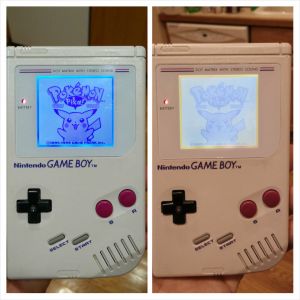
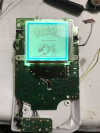
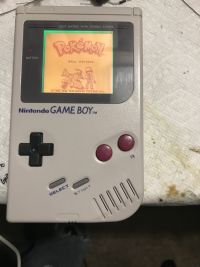
This page is a guide to walk you through adding a backlight to increase the visibility of your Game Boy screen. The optional "bivert" part of the mod greatly enhances visibility as shown in the comparison image on the right. The base for this guide was written by Roarke for RetroRGB.
Materials
- Backlight
- Bivert mod board (HIGHLY recommended)
- Solder, flux
- ChipQuik
- Solder Braid
- Isopropyl Alcohol (70-90%)
- A sharp razor blade
- Toothbrush and cotton swabs
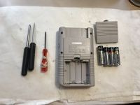
- Tri-wing screwdriver
- Phillip's head screwdriver
- Flush trimmers
- Heat shrink tubing
- Gloves (recommended to avoid smudging screen)
Screen Removal
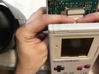
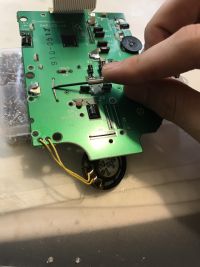
- Remove the six case screws. Earlier DMGs use Phillips Head screws, newer DMGs use Tri-Wing security screws. Pinch the ribbon cable connecting the LCD Board to the Motherboard with care and gently disconnect. Unscrew the LCD Board from the front half of the shell, remove the 10 Phillips Head screws, place the LCD Board on something that can support the LCD Board without putting any pressure on the ribbon cable.
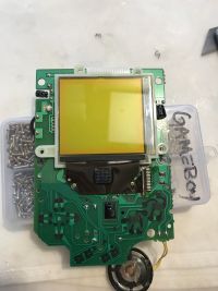
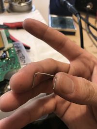
- You'll find two small Phillips Head screws and a staple that holds the Vertical ribbon cable to the LCD Board. On the backside of a board bend the two legs of the staple upward, flip the LCD Board and remove the two screws. Pry the staple up a little.
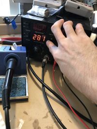
- One end of the staple is soldered to the board, get it good and fluxed up, place your solder braid on the solder joint, and wick away as much solder as possible. Then, heat it up with your iron and gently pull the staple out. Then, turn your iron down to 200C.
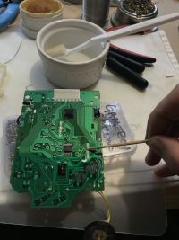
- Before doing anything, dip a cotton swab in your Isopropyl Alcohol and clean the pins of the vertical ribbon cable by moving the cotton swab gently in the same direction as the pins. This is to remove any contaminants on the old solder joints.
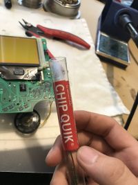
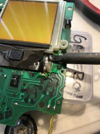
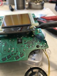
- For this step, you will need to use ChipQuik and preferably a knife tip on your soldering iron. This will lower the melting point of the solder to around 180C-200C and allow the solder to remain molten for longer, which is great for removing sensitive components with many pins. Add flux to the pins followed by laying a line of unmelted ChipQuik across the pins.
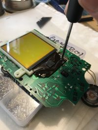
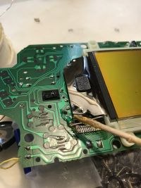
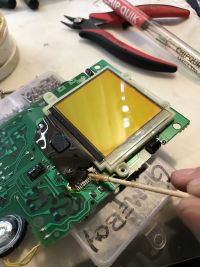
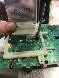
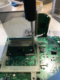
- Hold your iron so that the bevel of the tip is parallel to the board and oriented perpendicular to the pin direction, gently place the bevel on the ChipQuik, melting it, but don't allow your iron tip to actually touch the pins. The pins are EXTREMELY delicate and will break if you apply any pressure to them. Rock the ChipQuik solder blob back and forth along the pins while, gently, holding a small flat head screwdriver, or similar on hand tool, underneath the vertical ribbon cable. You're not forcing anything, but when the ChipQuik has completely mixed with all of the solder joints the vertical ribbon cable will naturally lift away from the LCD Board.
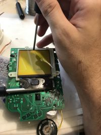
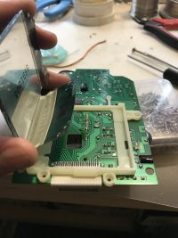
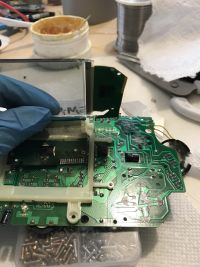
- Gently pry the screen up with a small flathead at the top of the screen (you'll see a small section of the plastic frame that accommodates the flathead). Open the screen like a book, supporting the horizontal ribbon cable, and remove the two double sided adhesive foam pieces.
- Remove the small black Philips head screw that mounts the horizontal ribbon cable. Repeat the same steps above to de-solder the horizontal cable. The main difference this time around is that you need to support the horizontal cable while working, without putting any pressure on it.
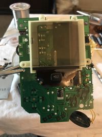
- Pinch the three clips of the plastic LCD frame on the back of the LCD Board and pop the frame off.
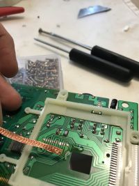
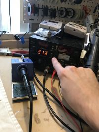
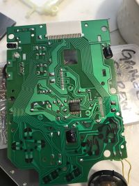
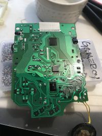
- Set your iron back up to soldering temperature to be just hot enough to easily melt your solder (315C-340C normally). Now we need to thoroughly remove any and all ChipQuik, both on the LCD board and on the LCD's ribbon cables. Flux the pins on the LCD board and use your solder braid to wick away the Chip Quik. There will still be a layer of ChipQuik on the pads, so you will need to re-tin the solder pads with standard solder, and again flux and wick away as much solder as possible. What you're doing here is mixing any remaining ChipQuik left on the pads with standard solder, then wicking it away to remove as much of the ChipQuik as possible. Rinse and repeat this process one or two times to completely remove the ChipQuik which, from here on out, should be considered as a contaminate.
- Repeat the same process on the pins on the LCD ribbon cables, but skipping the use of solder braid as the pins are extremely delicate and you run the risk of ripping the pins clean off of the ribbon cable. Instead, clean your soldering iron tip and place the bevel of the tip on the pins and gently "brush" away in the direction of the pins (be aware of solder splatter). The clean tip will wick away the ChipQuik. Clean your tip again, re-tin the pins with standard solder, use your tip to wick away the solder, clean your tip, and repeat this process 2-3 times on both the vertical and horizontal ribbon cables.
Component Replacement
There are various components that are soldered in behind the LCD. This is best time to test these components and replace the capacitors as these components are 30 years old and you may as well change them while you have access. Instructions for testing the diodes are located below.
- Capacitors C4: Replace with 47pF ceramic cap.
- Capacitors C6, C7, C8, C9, C10: Replace with Nichicon 1uF 50v electrolytic caps.
- Resistor R2: Replace with 100 ohm 1/8 watt resistor.
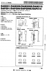
- Diodes DA1, DA2, DA3, DA4: Replace with DAN215 diodes.
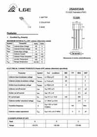
- Transistor Q1: Replace with 2SA933 PNP Transistor.
- The diode array is responsible for button presses and it is imperative that they are working correctly. The DAN215 Datasheet shows us that Pin 2 (the middle pin on the Diode) is a common negative, Pin 1 and Pin 3 each have a diode between them & the common ground. Good practice is to remove components and test them out of circuit, in this case because the LCD Board is not connected to the motherboard, and no buttons are being pressed, these diodes are not connected to any other components and can be tested without removing them.
- Set your multimeter to Diode function, find DA1, place your negative test lead on the common ground (pin 2) and put the positive test lead on Pin 1, you should get a voltage drop of 700 - 725 mV if it's good. If you get a reading of 1, it implies an open diode (double check your leads are hooked up correctly). If you hear a beep then you have continuity, implying a short. Do the same for Pin 3. Rinse and repeat for DA2, DA3 and DA4 replacing them as needed.
- Find Q1 and remove it from the circuit. Q1 is a 2SA933 PNP Transistor with pin 1 being the Emitter, pin 2 being the Collector, pin 3 being the base.
- Set your multimeter to Diode mode and test the following (this is for a PNP Transistor, NPNs will be done the same way but with different results). If any tests fail, replace Q1.
- Emitter to Base - Positive on Emitter, Negative on Base. You should see a voltage drop between 0.4V & 0.9V.
- Collector to Base - Positive on Collector, Negative on Base. You should see a voltage drop between 0.4V & 0.9V.
- Base to Emitter - Positive on Base, Negative on Emitter. You should see an "Over Limit" reading or something similar.
- Base to Collector - Positive on Base, Negative on Collector. You should see an "Over Limit" reading or something similar.
- Collector to Emitter - Positive on Collector, Negative on Emitter. You should see an Over Limit reading or something similar. Now reverse the test leads, Negative on Collector, Positive on Emitter. You should also see an Over Limit reading or something similar.
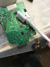
- After replacing any needed components, thoroughly clean the LCD Board with Isopropyl and a toothbrush, be sure to keep the brush clean, and follow up with paper towels or cotton swabs before the isopropyl evaporates, as it'll leave sticky flux residue behind.
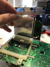
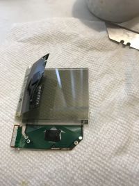
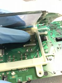
- While you're here, you can also easily leverage the rear polarizing/reflective film, without damaging the horizontal ribbon cable, and will give you full access to the inside of the screen to clean it corner to corner with a microfiber cloth.
Separating the Screen
From here on it out, it's recommended to wear gloves to prevent getting fingerprints on the screen.
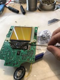
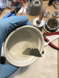
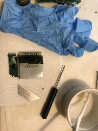
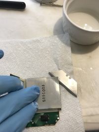
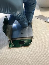
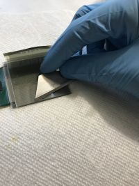
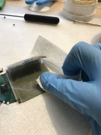
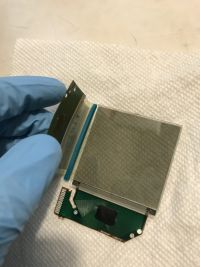
- Dip your razor blade in isopropyl alcohol and slide it between the LCD and the reflective film, starting at the corner, with the bevel of the blade flat against the LCD. Get the blade in about a 1/3 of an inch or until you can pinch the lifted corner of the reflective film. Pinch the reflective film and pull it in one smooth motion, the quicker and the smoother the film is pulled, the cleaner the screen will be, but fear not if there's adhesive left on the LCD, just dip your blade in Isopropyl and gently remove the adhesive. Follow up with a paper towel dipped in alcohol, then a dry paper towel, and preferably with a spray of compressed air to ensure it's dry.
- This would be the time to address any horizontal line issues your screen may have. A video tutorial for this can be found on RetroRGB's channel.
- Pop the LCD frame back onto the LCD board and flux the solder pads. Place the horizontal cable roughly in the right place, and screw the Horizontal set screw partially in, but not all the way. Tack the pins in with your iron, using the bevel of the iron tip. Screw the set screw in all the way, and reflow the solder on the pins.
- Using a cotton swab and alcohol, clean up the flux.
(Optional) Bivert Mod
If you opted for a bivert mod PCB, use the instructions below to install it. Otherwise, skip to the next section.
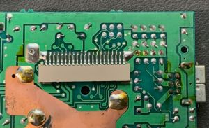
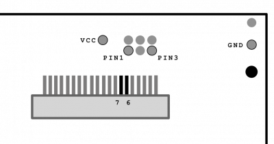
- Gently heat and lift pin 6 and pin 7 of the ribbon cable port.
- Slide the bivert board under the lifted pins and align the the pins as well as VCC, PIN1, and PIN3. Note that the board will hang off of the edge of the board.
- Solder the two lifted pins, as well as the VCC, PIN1, and PIN3 solder joints. Using flux will help avoid bridges between the two lifted pins.
- Solder a wire from the GND pad on the PCB and the GND pad in the diagram above.
Installing the Backlight
| TODO: Expand the "how" on wiring up the backlight. |
- Wire up your backlight and place it behind the screen. You will want to place the backlight in before soldering the vertical ribbon cable, because the backlight is a bit thicker than the space beneath the screen, if you solder up the vertical cable without the backlight in, it'll add tension/stress to the pins on the vertical ribbon cable, which will cause problems down the road.
- Close the screen and repeat the same process for the vertical ribbon cable. You can now wire up the backlight to either a backlight controller, to C2, or directly to the DC-DC board, but best practice would be to install an auxiliary 5V Buck/Boost regulator and power all mods off of the aux 5V rail. Button everything back up, which if you've made it this far should be easy and quick!
