Dreamcast:BIOS Replacement Mod: Difference between revisions
Jump to navigation
Jump to search
No edit summary |
mNo edit summary |
||
| Line 16: | Line 16: | ||
# To write-enable the BIOS (to be able to update the BIOS via software in the future), solder a wire from pin 44 on the new BIOS to pin B14 of the GD-ROM connector. There are alternate locations for a cleaner install, but are generally more difficult to solder to. | # To write-enable the BIOS (to be able to update the BIOS via software in the future), solder a wire from pin 44 on the new BIOS to pin B14 of the GD-ROM connector. There are alternate locations for a cleaner install, but are generally more difficult to solder to. | ||
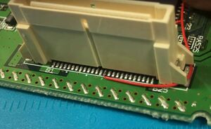
#: <div class="inline-thumb">[[File:Dreamcast BIOS Replacement GD-ROM Pin.jpg|thumb|GD-ROM pin B14]] [[File:Dreamcast BIOS Replacement Wired.jpg|thumb|Alternate pin]]</div> | #: <div class="inline-thumb">[[File:Dreamcast BIOS Replacement GD-ROM Pin.jpg|thumb|GD-ROM pin B14]] [[File:Dreamcast BIOS Replacement Wired.jpg|thumb|Alternate pin]]</div> | ||
# Clean all soldered areas with isopropyl alcohol and allow it to dry. | |||
# Plug in the fan and GD-ROM (or GD-EMU) and test to make sure that it boots. Ensure that you prop up the GD-ROM or GD-EMU so that it is flat and level, as it will otherwise not make a proper connection. | # Plug in the fan and GD-ROM (or GD-EMU) and test to make sure that it boots. Ensure that you prop up the GD-ROM or GD-EMU so that it is flat and level, as it will otherwise not make a proper connection. | ||
Revision as of 17:54, 27 February 2024
If you want region-free game loading, to load burned game backups on a model VA2 Dreamcast, to force all games to boot with VGA output, or your BIOS chip is simply corrupt; you can replace the Dreamcast BIOS chip with a new one.
Installation
A video detailing this process can be found on ModzvilleUSA's YouTube channel.
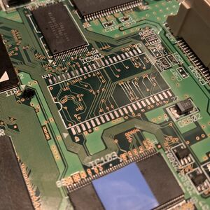
- Disassemble the Dreamcast and locate the BIOS chip IC501 (labelled MPR-21931-X1, MPR-21933-X1, or MPR-21931-X2).
- Turn the Dreamcast on and use a multimeter to measure pin 23.
- If it measures around 3.3V, you will need a 3.3V BIOS chip.
- If it measures around 5V, you will need a 5V BIOS chip.
- Remove the existing BIOS chip. You may find the Replacing ICs page helpful.
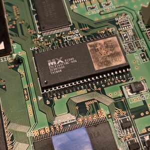
- Solder in the new BIOS chip.
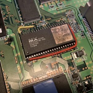
- Solder a wire from pin 1 of the new BIOS to pin 23.
- To write-enable the BIOS (to be able to update the BIOS via software in the future), solder a wire from pin 44 on the new BIOS to pin B14 of the GD-ROM connector. There are alternate locations for a cleaner install, but are generally more difficult to solder to.
- Clean all soldered areas with isopropyl alcohol and allow it to dry.
- Plug in the fan and GD-ROM (or GD-EMU) and test to make sure that it boots. Ensure that you prop up the GD-ROM or GD-EMU so that it is flat and level, as it will otherwise not make a proper connection.


