FunnyPlaying GBC Button LED Kit
Jump to navigation
Jump to search
m (→Installation) |
m (→Installation) |
||
| (3 intermediate revisions by the same user not shown) | |||
| Line 6: | Line 6: | ||
== Installation == | == Installation == | ||
[[File:GBC_Button_LED_Mod.jpg|thumb|Installation diagram]] | |||
# Lay the flex PCB over the buttons area and tape it into place at the top and bottom, covering all exposed motherboard pads between the voltage regulator and the speaker. Ensure that the circle cutouts for "A", "B", "Start", and "Select" all have the pad on the motherboard showing. | |||
# Solder the bottom-most point on the flex PCB (marked `1` in the diagram to the right). This is to keep the flex board laying flat. | |||
# Solder the large C-shaped pads near the upper corners with the "C" pad and "Start/Select" pads (marked `2` and `3`). | |||
# Solder the Start and Select pins (marked `4` and `5`) to the flex PCB toward the bottom of the PCB. | |||
# Cover the large A button pads with tape then solder the nearby "A" pin (marked `6`) to the flex PCB. | |||
# Cover the large B button pads with tape then solder the nearby "B" pin (marked `7`) to the flex PCB. | |||
# Optional: If you are using a lithium ion rechargeable battery, you can solder wire from point C (marked `8A`) at the top-right of the flex PCB to the SW1VCC point (marked `8B`). This is used for low battery detection. Do not solder this if using regular batteries or it will always show low battery lights. | |||
{{Note|Although it is connected to circuitry, do not solder pad "D" (marked as point 8 or DNG on the official site). FunnyPlaying's support has confirmed that this point should not be used.}} | |||
{{br}} | |||
== Usage == | == Usage == | ||
| Line 24: | Line 28: | ||
* To select a color, enter RGB mode, then hold Select+A or Select+B until it reaches the color you want, then let go. | * To select a color, enter RGB mode, then hold Select+A or Select+B until it reaches the color you want, then let go. | ||
* To select the brightness level, enter RGB mode then press Select+A+B, then hold Select+A or Select+B until it reaches the brightness level you want, then let go. | * To select the brightness level, enter RGB mode then press Select+A+B, then hold Select+A or Select+B until it reaches the brightness level you want, then let go. | ||
* To turn off the low battery indicator, hold Select+A+B for two seconds. | |||
Latest revision as of 13:00, 4 April 2024
The FunnyPlaying GBC Button LED Kit is a mod kit that adds LEDs around the buttons of your Game Boy Color.
Note that this offers new pads for Start and Select, so if you are doing a backlight mod or planning on using a replacement LCD screen, you should install the LED kit first as these pads will be easier to connect to for Start/Select. It should be noted that the labels on the flex may be swapped, so you should test continuity for the Start and Select pads at the top of the flex board and the Start and Select pins at the bottom of the flex board.
| If you are using the transparent flex board, avoid using heat above 183°C (361.4°F), as it is less heat resistant than the orange or white flex boards. |
Installation
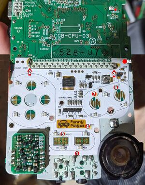
- Lay the flex PCB over the buttons area and tape it into place at the top and bottom, covering all exposed motherboard pads between the voltage regulator and the speaker. Ensure that the circle cutouts for "A", "B", "Start", and "Select" all have the pad on the motherboard showing.
- Solder the bottom-most point on the flex PCB (marked
1in the diagram to the right). This is to keep the flex board laying flat. - Solder the large C-shaped pads near the upper corners with the "C" pad and "Start/Select" pads (marked
2and3). - Solder the Start and Select pins (marked
4and5) to the flex PCB toward the bottom of the PCB. - Cover the large A button pads with tape then solder the nearby "A" pin (marked
6) to the flex PCB. - Cover the large B button pads with tape then solder the nearby "B" pin (marked
7) to the flex PCB. - Optional: If you are using a lithium ion rechargeable battery, you can solder wire from point C (marked
8A) at the top-right of the flex PCB to the SW1VCC point (marked8B). This is used for low battery detection. Do not solder this if using regular batteries or it will always show low battery lights.
| Although it is connected to circuitry, do not solder pad "D" (marked as point 8 or DNG on the official site). FunnyPlaying's support has confirmed that this point should not be used. |
Usage
- A+B for two seconds: Toggle between LED color modes.
- Breathing mode: Slow pulsing that cycles through all colors
- RGB mode: Solid color. Hold Select and A or B to change colors.
- White mode: Solid white.
- OFF: All LEDs are off.
- To select a color, enter RGB mode, then hold Select+A or Select+B until it reaches the color you want, then let go.
- To select the brightness level, enter RGB mode then press Select+A+B, then hold Select+A or Select+B until it reaches the brightness level you want, then let go.
- To turn off the low battery indicator, hold Select+A+B for two seconds.
