Master System:Video Output Notes: Difference between revisions
(Largely copying what I wrote in SMS Power's wiki; also added more info regarding the French consoles) |
|||
| Line 1: | Line 1: | ||
== RGB Cable Components == | |||
For most SMS consoles with RGB output, all RGB cables that use CSYNC should have a 470 ohm resistor and a 10 uF–220 uF 10 V minimum capacitor with the positive leg facing the console on the sync line (pin 7). A 10 uF capacitor is all that's needed, but it is also very common for people to use 220 uF. Either way, the voltage rating shouldn't be below 10 V. Composite video can also be used for sync. The red, green and blue signals must have 75 ohm in-line resistors as the picture will be too bright and washed out without them. | |||
== Mark III == | == Mark III == | ||
The Sega Mark III is the original version of the Master System hardware and was the first Sega console to have a video output better than RF, featuring both composite and RGB output sent through an 8-pin DIN connector (specifically the 262 degree or "U-shape" variant). While the composite output is suitable for practically any display without external components, the RGB output is not, as it comes directly from the VDP and | The Sega Mark III is the original version of the Master System hardware and was the first Sega console to have a video output better than RF, featuring both composite and RGB output sent through an 8-pin DIN connector (specifically the 262 degree or "U-shape" variant). While the composite output is suitable for practically any display without external components, the RGB output is not, as it comes directly from the VDP and requires amplification. A cable with a built-in amplifier such as the French SCART cable (detailed in one of the sections below) or an HD Retrovision cable can be used, or the console itself can be modified with an internal amplifier, making it compatible with standard Master System and model 1 Genesis/Mega Drive RGB cables. | ||
To generate composite video, the Mark III's video encoder, a ROHM BA7230LS, converts the RGB into ''component'' video, which is then fed back into the encoder to create a composite video signal. The resulting signal is bright but is rather blurred and not quite as saturated as later Master Systems. Given that the BA7230LS generates component video, it may be possible to modify a Mark III for this output, but no such attempt has been made as of yet. | To generate composite video, the Mark III's video encoder, a ROHM BA7230LS, converts the RGB into ''component'' video, which is then fed back into the encoder to create a composite video signal. The resulting signal is bright but is rather blurred and not quite as saturated as later Master Systems. Given that the BA7230LS generates component video, it may be possible to modify a Mark III for this output, but no such attempt has been made as of yet. | ||
| Line 7: | Line 9: | ||
The Mark III's composite output can be slightly improved by connecting pin 20 of the BA7230LS to ground using a 1 uF capacitor. Pin 20 is an unused composite video input, which according to the [https://media.digikey.com/pdf/Data%20Sheets/Rohm%20PDFs/BA7230LS.pdf datasheet] must not be left floating (disconnected); there are footprints for the necessary components on the Mark III's motherboard, but for some unknown reason these were left unpopulated. This can be remedied by populating C96 with a 1 uF capacitor and R97 with a jumper link. | The Mark III's composite output can be slightly improved by connecting pin 20 of the BA7230LS to ground using a 1 uF capacitor. Pin 20 is an unused composite video input, which according to the [https://media.digikey.com/pdf/Data%20Sheets/Rohm%20PDFs/BA7230LS.pdf datasheet] must not be left floating (disconnected); there are footprints for the necessary components on the Mark III's motherboard, but for some unknown reason these were left unpopulated. This can be remedied by populating C96 with a 1 uF capacitor and R97 with a jumper link. | ||
== | == Model 1 Consoles with V7040 Encoder == | ||
The earliest revisions of the model 1 Master System use a Sony V7040 video encoder chip, which takes in the RGB output from the VDP and converts it to composite video, which is sent to the RF modulator and an 8-pin DIN connector for AV output. The V7040 also offers amplified RGB output capable of driving a standard 75 ohm load. | |||
However, consoles with this encoder output RGB that is dim compared to later revisions because Sega used different values for the resistors on the RGB signals going into the V7040. In this case, Sega used 3.3k ohm for both the series resistors and the pulldown resistors, whereas 2.2k ohm and 4.7k ohm were used for these resistors respectively on later revisions that used a CXA1145. This may have been a mistake on Sega's part as 3.3k ohm resistors are correct for the BA7230LS encoder in the Mark III, which expects the amplitude of the RGB signals to be 0.7 Vpp. The V7040 and the later CXA1145 expect 1.0 Vpp, so this creates the dim RGB output on these early revisions. | |||
To get brighter RGB, substitute R6 through R8 with 2.2k ohm resistors and R9 through R11 with 4.7k ohm resistors. This will also have the side effect of brightening the composite video signal and making it more stable for certain upscalers like the [[AV:RetroTINK-5X Pro|RetroTINK-5X Pro]]. | |||
<gallery> | |||
File:V7040RGBBefore.png|The stock RGB output of an early revision Master System with the V7040 encoder, using a standard Genesis/SMS SCART cable. Due to Sega using incorrect resistor values in the voltage divider circuit, the image is rather dim. | |||
File:V7040RGBAfter.png|With the resistor values substituted, the RGB output is much brighter. | |||
</gallery> | |||
== French Consoles and RGB == | |||
French Master System and Master System II consoles offer RGB output and were shipped with a special SCART cable. Unlike other French consoles that offered RGB converted from composite, RGB on the French SMS II is native RGB output directly from the VDP. However, because the RGB output comes straight from the VDP (much like the Mark III), it is not amplified and requires the SCART cable that came bundled with the console. This is because the SCART cable contains an amplifier circuit which makes this RGB output suitable for most displays. These consoles also do not output composite video as they do not contain a video encoder chip, and the DIN connector pin which normally carries this signal is unused. | |||
The | The HD Retrovision cable for the Genesis is compatible with these consoles with the use of [https://retrostuff.ca/collections/hd-retrovision-cables/products/model-1-mega-drive-a-v-port-adapter-france-switzerland-only a special adapter], which allows the cable to use the TTL sync signal from the DIN connector. The HDRV cable's contrast switch can also be used to make up for the low brightness. An RGB bypass board can also be easily wired in to allow these consoles to use standard RGB cables, and most bypass boards are capable of outputting 75 ohm composite sync so the RGB output can be safely used on devices which could otherwise be damaged by using TTL sync. | ||
With the right parts, the missing video circuitry on French consoles can be repopulated and they can be converted into outputting proper NTSC composite video with amplified RGB. However, this may not be cost-effective depending on the particular console (especially with model 1s). | |||
== Japanese Version (MK-2000) == | == Japanese Version (MK-2000) == | ||
| Line 22: | Line 38: | ||
File:JPSMSCorrectedRGB.png|With the internal components removed, the RGB output is considerably brighter. | File:JPSMSCorrectedRGB.png|With the internal components removed, the RGB output is considerably brighter. | ||
</gallery> | </gallery> | ||
[[Category:Master System]] | [[Category:Master System]] | ||
Revision as of 07:44, 24 June 2024
RGB Cable Components
For most SMS consoles with RGB output, all RGB cables that use CSYNC should have a 470 ohm resistor and a 10 uF–220 uF 10 V minimum capacitor with the positive leg facing the console on the sync line (pin 7). A 10 uF capacitor is all that's needed, but it is also very common for people to use 220 uF. Either way, the voltage rating shouldn't be below 10 V. Composite video can also be used for sync. The red, green and blue signals must have 75 ohm in-line resistors as the picture will be too bright and washed out without them.
Mark III
The Sega Mark III is the original version of the Master System hardware and was the first Sega console to have a video output better than RF, featuring both composite and RGB output sent through an 8-pin DIN connector (specifically the 262 degree or "U-shape" variant). While the composite output is suitable for practically any display without external components, the RGB output is not, as it comes directly from the VDP and requires amplification. A cable with a built-in amplifier such as the French SCART cable (detailed in one of the sections below) or an HD Retrovision cable can be used, or the console itself can be modified with an internal amplifier, making it compatible with standard Master System and model 1 Genesis/Mega Drive RGB cables.
To generate composite video, the Mark III's video encoder, a ROHM BA7230LS, converts the RGB into component video, which is then fed back into the encoder to create a composite video signal. The resulting signal is bright but is rather blurred and not quite as saturated as later Master Systems. Given that the BA7230LS generates component video, it may be possible to modify a Mark III for this output, but no such attempt has been made as of yet.
The Mark III's composite output can be slightly improved by connecting pin 20 of the BA7230LS to ground using a 1 uF capacitor. Pin 20 is an unused composite video input, which according to the datasheet must not be left floating (disconnected); there are footprints for the necessary components on the Mark III's motherboard, but for some unknown reason these were left unpopulated. This can be remedied by populating C96 with a 1 uF capacitor and R97 with a jumper link.
Model 1 Consoles with V7040 Encoder
The earliest revisions of the model 1 Master System use a Sony V7040 video encoder chip, which takes in the RGB output from the VDP and converts it to composite video, which is sent to the RF modulator and an 8-pin DIN connector for AV output. The V7040 also offers amplified RGB output capable of driving a standard 75 ohm load.
However, consoles with this encoder output RGB that is dim compared to later revisions because Sega used different values for the resistors on the RGB signals going into the V7040. In this case, Sega used 3.3k ohm for both the series resistors and the pulldown resistors, whereas 2.2k ohm and 4.7k ohm were used for these resistors respectively on later revisions that used a CXA1145. This may have been a mistake on Sega's part as 3.3k ohm resistors are correct for the BA7230LS encoder in the Mark III, which expects the amplitude of the RGB signals to be 0.7 Vpp. The V7040 and the later CXA1145 expect 1.0 Vpp, so this creates the dim RGB output on these early revisions.
To get brighter RGB, substitute R6 through R8 with 2.2k ohm resistors and R9 through R11 with 4.7k ohm resistors. This will also have the side effect of brightening the composite video signal and making it more stable for certain upscalers like the RetroTINK-5X Pro.
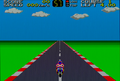
The stock RGB output of an early revision Master System with the V7040 encoder, using a standard Genesis/SMS SCART cable. Due to Sega using incorrect resistor values in the voltage divider circuit, the image is rather dim.
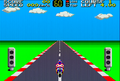
With the resistor values substituted, the RGB output is much brighter.


French Consoles and RGB
French Master System and Master System II consoles offer RGB output and were shipped with a special SCART cable. Unlike other French consoles that offered RGB converted from composite, RGB on the French SMS II is native RGB output directly from the VDP. However, because the RGB output comes straight from the VDP (much like the Mark III), it is not amplified and requires the SCART cable that came bundled with the console. This is because the SCART cable contains an amplifier circuit which makes this RGB output suitable for most displays. These consoles also do not output composite video as they do not contain a video encoder chip, and the DIN connector pin which normally carries this signal is unused.
The HD Retrovision cable for the Genesis is compatible with these consoles with the use of a special adapter, which allows the cable to use the TTL sync signal from the DIN connector. The HDRV cable's contrast switch can also be used to make up for the low brightness. An RGB bypass board can also be easily wired in to allow these consoles to use standard RGB cables, and most bypass boards are capable of outputting 75 ohm composite sync so the RGB output can be safely used on devices which could otherwise be damaged by using TTL sync.
With the right parts, the missing video circuitry on French consoles can be repopulated and they can be converted into outputting proper NTSC composite video with amplified RGB. However, this may not be cost-effective depending on the particular console (especially with model 1s).
Japanese Version (MK-2000)
The Japanese Master System (often referred to as the MK-2000) does not require any components on the CSYNC line. When connected to a display or processor, it will output around 350 mV without anything else needed. In fact, all four lines (red, green, blue and sync) all have the necessary components on the motherboard, so the RGB cable will just be a full pass-through cable. This is the opposite of all other SMS revisions, and using RGB cables meant for these consoles on the MK-2000 will result in a dimmer picture. The HD Retrovision cable can compensate for this with its contrast switch, but this can pose a problem otherwise.
Alternatively, four sets of 75 ohm resistors and 100 uF capacitors in the console can be removed and replaced with jumper links, allowing for the use of regular SMS RGB cables. Capacitors C41 through C43 and C45, and resistors R41 through R43 and R45 must be removed, then jumper links can be added so the output pins on the CXA1145 go directly to the DIN connector. The jumpers must be connected as shown in the photo below; do not remove C44 and R44 as those are for composite video. Note that the solder pads for these components are very fragile, so great care must be taken when desoldering these components.
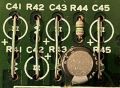
The extra resistors and capacitors for RGBS on this Japanese SMS have been removed and replaced with jumpers so standard cables can be used.
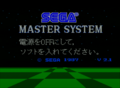
This is the stock RGB output from a Japanese SMS using a standard Genesis/SMS SCART cable.
With the internal components removed, the RGB output is considerably brighter.


