Jaguar:Behind Jaggy Lines (BJL) Mod: Difference between revisions
Jump to navigation
Jump to search
(Created page with "thumb|BJL debug bios Behind Jaggy Lines [BJL] is a method to load a debug BIOS, capable of receiving a single ROM sent over the second controller port via a special cable. It is generally used for homebrew development, but can be used as a method to load homebrew games. [http://www.mdgames.de/bjlmod.htm Original guide] by [https://www.monlynx.de/ Bastian Schick], pictures by Matthias Domin. == Required Materials == You need: * An EPROM type 27c...") |
mNo edit summary |
||
| Line 5: | Line 5: | ||
You need: | You need: | ||
* An EPROM type 27c010 or 27c1001 (this is 128K x 8) loaded with the BJL BIOS (DEBJAG.IMG) | * An EPROM type 27c010 or 27c1001 (this is 128K x 8) loaded with the BJL BIOS (DEBJAG.IMG) (or [[File:Bjl0702.bin]] ???) | ||
* A 32-pin socket | * A 32-pin socket | ||
* A SPDT switch (on-on) | * A SPDT switch (on-on) | ||
Latest revision as of 00:03, 7 October 2024

Behind Jaggy Lines [BJL] is a method to load a debug BIOS, capable of receiving a single ROM sent over the second controller port via a special cable. It is generally used for homebrew development, but can be used as a method to load homebrew games. Original guide by Bastian Schick, pictures by Matthias Domin.
Required Materials
You need:
- An EPROM type 27c010 or 27c1001 (this is 128K x 8) loaded with the BJL BIOS (DEBJAG.IMG) (or File:Bjl0702.bin ???)
- A 32-pin socket
- A SPDT switch (on-on)
- Two 4k7 resistors (1/4W)
- Soldering iron, solder, and wire
- A VGA port (Jaguar port) and parallel port
Console Modification
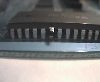
- Open your Jaguar console and remove the shield. Locate the BIOS chip near the power socket (M27C1001, labelled U35 on the motherboard).
- Cut /CE (pin 22) as close as possible to the PCB and bend it upwards.
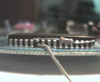
- Solder a resistor to the lifted pin to pin 32 (Vcc).
- On the 32-pin socket, bend pin 22 upwards.
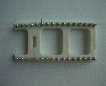
- Solder the socket onto the BIOS chip, with the exception of pin 22.
- Solder the second resistor to pin 22 of the socket and to pin 32 of the BIOS chip.
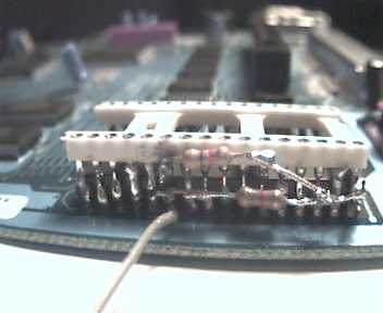
- Solder 3 wires to the switch:
- The middle to the pin 22 hole on the PCB
- To pin 22 of the BIOS chip
- To pin 22 of the socket
- Switch your Jaguar ON to test. Then, turn it off, change the switch position, and turn it ON a second time. In one position nothing should happen, in the other, it should boot normally.
- If nothing happens in either position, check all steps and check for short circuits.
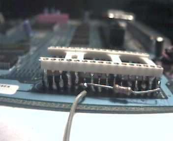
- Insert your EPROM into the socket and switch your Jaguar on. It should now show a red text screen with a 68k register-dump and a blue or red border.
- Mount the switch. Common places are:
- Near the power plug (requires cutting metal shield):
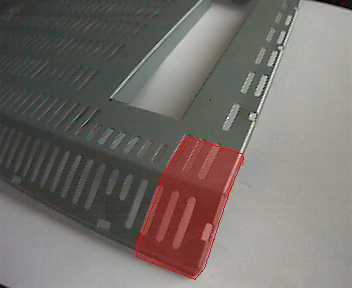
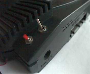
- Near the joypad port 2:
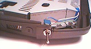
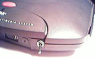
- Near the power plug (requires cutting metal shield):


BJL Cable
Create a cable with this wiring. The Jaguar end is the same connector as a VGA cable, and the other end is a parallel cable to connect to a PC or Parallel-to-USB adapter.
