RetroTINK-4K/ja
(Created page with "利用可能なオプションは次のとおり: {| class="wikitable" !Pixel Aspect Ratio !Description !Display Aspect Ratio Use-Case |- |'''4:3 (PAR)''' |Uses the common 4:3 Pixel Aspect Ratio, displaying the pixels slightly wider than squares. |Pre-HDMI® video game consoles, which expect to be displayed on the 4:3 DAR of CRT televisions. |- |'''16:9 (PAR)''' |Uses the 16:9 Pixel Aspect Ratio, displaying the pixels even wider than 4:3 (PAR). |Pre-HDMI® games and syst...") |
(Created page with "自分でマスクを作りたい場合は、このページの Custom CRT Masks にいけばよい。") |
||
| (31 intermediate revisions by the same user not shown) | |||
| Line 1,021: | Line 1,021: | ||
|'''Vertical Only''' | |'''Vertical Only''' | ||
|AUX 1 | |AUX 1 | ||
| ゲーム画像の上部と下部に "上部トリム" と"下部トリム" | | ゲーム画像の上部と下部に "上部トリム" と"下部トリム" を自動的に調整する。左トリムや右トリムは調整されず、アスペクト補正も変更されない。 | ||
|- | |- | ||
|'''Full Crop to 4:3''' | |'''Full Crop to 4:3''' | ||
| Line 1,061: | Line 1,061: | ||
複数のピクセル アスペクト比を使用できるデバイスを使用している場合、ゲームがディスプレイに表示されたときに正しく表示されるようにそのデバイスをRT4Kと正しく適合するように設定することが重要である。 | 複数のピクセル アスペクト比を使用できるデバイスを使用している場合、ゲームがディスプレイに表示されたときに正しく表示されるようにそのデバイスをRT4Kと正しく適合するように設定することが重要である。 | ||
==== スケーリングモード(Scaling Mode) ==== | |||
= | スケーリングモードでは自動スケーリングモードを選択したり、手動スケーリングのアスペクト比制約を変更したりできる: | ||
* '''Auto Fill''' - 選択したアスペクト補正のアスペクト比に基づいて画面を埋める。 | |||
* '''Auto Fill''' - | * '''Proportional''' - アスペクト補正で選択したアスペクト比を維持するために水平係数を自動的に調整しながら垂直係数を調整できる。 | ||
* '''Proportional''' - | |||
* '''Free-Form''' - Untethers the Vertical Factor and Horizontal Factor to allow values outside of the Aspect Correction setting. This setting lets you use the [[AV:RetroTINK-4K#Scaling Factors (Transform Tools)|Vert. Factor and Hori. Factor]] settings to freely transform the image, like on the RetroTINK-5X. | * '''Free-Form''' - Untethers the Vertical Factor and Horizontal Factor to allow values outside of the Aspect Correction setting. This setting lets you use the [[AV:RetroTINK-4K#Scaling Factors (Transform Tools)|Vert. Factor and Hori. Factor]] settings to freely transform the image, like on the RetroTINK-5X. | ||
* '''Auto Fill Integer''' - Scales the Vertical Factor and Horizontal Factor to the highest possible integer value without exceeding the screen boundaries, while also respecting the ratio selected in Aspect Correction. We highly recommend using the [[AV:RetroTINK-4K#Input Crop|cropping tools]] to ensure the picture can be as large as possible while using this scaling mode. | * '''Auto Fill Integer''' - Scales the Vertical Factor and Horizontal Factor to the highest possible integer value without exceeding the screen boundaries, while also respecting the ratio selected in Aspect Correction. We highly recommend using the [[AV:RetroTINK-4K#Input Crop|cropping tools]] to ensure the picture can be as large as possible while using this scaling mode. | ||
このスケーリングモードを使用しているときに画像を可能な限り大きくするには、 [[AV:RetroTINK-4K#Input Crop|cropping tools]] を使用することを推奨する。 | |||
==== Scaling Factors (Transform Tools) ==== | ==== Scaling Factors (Transform Tools) ==== | ||
'''Horizontal Factor''' と '''Vertical Factor''' により画像を水平方向または垂直方向に伸縮および変換できる。各係数には、それぞれ乗数値、入力解像度、および出力解像度が表示される。 | |||
どれが使用可能かは、[[AV:RetroTINK-4K#Scaling Mode|Scaling Mode]] がどのオプションに設定されているかによって異なる。Proportionalでは垂直係数がロック解除され、Free-Formでは垂直係数と水平係数の両方がロック解除される。 | |||
この関数は簡単な式で表すことができる: ''[Input Resolution] X [Multiplier] = [Output Resolution]''. | |||
{| class="wikitable" | {| class="wikitable" | ||
|- | |- | ||
! colspan="4" style="font-weight:bold;" |Horizontal and Vertical | ! colspan="4" style="font-weight:bold;" |Horizontal and Vertical Factor例 | ||
|- style="font-style:italic;" | |- style="font-style:italic;" | ||
|Axis | |Axis | ||
| Line 1,104: | Line 1,096: | ||
|} | |} | ||
===Buffer=== | ===Buffer=== | ||
RetroTINK-4K では画面に出力する前にバッファするビデオの量を設定できる。バッファは [[#Sync_Lock|Sync Lock]] モードと連動して、全体的な遅延を決定する主な要因となる。 | |||
* '''Min. Lag''' - バッファを最低限のビデオライン数のみ保存するように設定する。このオプションにより、レイテンシが最小になる。 | |||
* '''1/2 Frame''' - 常にフレームの半分をバッファリングする。 | |||
* '''1 Frame''' - 常にフレーム全体をバッファリングする。 | |||
< | Min. Lagは通常は互換性があるが、画面ティアリングが発生する特殊なケースに遭遇した場合は、これを「1/2 Frame」または「1 Frame」に設定してみればよい。<br> | ||
{{Note|逆テレシネなどの特定のムービーモードでは、RetroTINK-4K が自動的にフル フレームをバッファリングする。}} | |||
===マスキングカラー(Masking Color)=== | |||
== | マスキング・カラーの設定では "Scaling/Crop" メニューに表示されるマスクの色を調整できる。デフォルトでは赤0、緑0、青31である。また、マスキングカラーをクロップメニューにのみ表示するか、常に表示するか(RT4Kメニューが表示されていない場合でも)を変更できる。 | ||
== 処理とエフェクト(Processing and Effects) == | |||
=== | 処理とエフェクトのセットアップメニューでは、ピクセル補間を調整したり、スキャンラインやCRTマスクを追加したりできる。 | ||
==== スキャンラインプリセットはどこにあるか? ==== | |||
RetroTINK-5Xをいつも使っている人なら、このメニューに入ってプリセットがないことに驚くかもしれない。これはSDカードにプロファイルとして保存されているから。 | |||
* 同梱のCRTプリセットを読み込むには、メインメニューからProfiles > Load from File > HDR CRT Simulationと進み、使いたいものを選ぶ。 | |||
CRTプリセットをプロファイルとして "バンドル" することは、RetroTINK-5X のユーザーにとっては奇妙に思えるかもしれない (CRTプリセットは最適なサンプリング プロファイルに簡単に適用できる)。ただし、最終結果にはあまり影響しない。CRTディスプレイは、美観上本質的に少しぼやけている (PVM や BVM であっても)、そのため、汎用サンプリングを使用することはまったく問題ない。デジタルソースを使用していて、それをデシメーションしている場合 (Nintendo Switch Online や HDMI® 改造システムなど)、[[AV:RetroTINK-4K#Interpolation|Horizontal Interpolation Kernel]] や [[AV:RetroTINK-4K#Horizontal Blur|Horizontal Blur]] 機能を使用してぼかしをシミュレートすることを推奨する。 | |||
上記の唯一の例外は、LCD スキャンラインを使用している場合である。画像を一定の数値 (4.000 倍や 5.000 倍など) で拡大しないと、各ピクセルを分割する細い線が正しく表示されない。 | |||
=== | |||
==== | === 補間(Interpolation) === | ||
====垂直カーネルと水平カーネル(Vertical and Horizontal Kernel)==== | |||
映像処理に関連する補間は、入力に与えられた視覚情報をより多く出力に作り出す技術である。これらの処理は、より視覚的にまとまりのある画像を作成するのに役立ち、画像がスクロールしているときの揺らぎなどの効果を低減する。RetroTINK-4Kは、垂直軸と水平軸に独立して適用できる補間オプションを提供している。 | |||
* '''Bilinear Sharp''' - The image is scaled up the maximum integer factor that is within the output size using Nearest Neighbor followed by a bilinear scale to the final output size. This option provides sharp pixels without shimmer at non-integer scaling factors. | * '''Bilinear Sharp''' - The image is scaled up the maximum integer factor that is within the output size using Nearest Neighbor followed by a bilinear scale to the final output size. This option provides sharp pixels without shimmer at non-integer scaling factors. | ||
* '''Bilinear Medium''' - The image is scaled up to the closest integer that is smaller or equal to the output pixels divided by 2 using Nearest Neighbor followed by a bilinear scale to the final output size. This option is somewhat softer than Bilinear Sharp but still sharper than regular Bilinear. | * '''Bilinear Medium''' - The image is scaled up to the closest integer that is smaller or equal to the output pixels divided by 2 using Nearest Neighbor followed by a bilinear scale to the final output size. This option is somewhat softer than Bilinear Sharp but still sharper than regular Bilinear. | ||
| Line 1,150: | Line 1,129: | ||
* '''Lanczos2''' and '''Lanczos3''' - Interpolation using the Lanczos family of scaling algorithms. Lanczos is a popular algorithm that provides good results for natural imagery (i.e. movies) and most 3D games. | * '''Lanczos2''' and '''Lanczos3''' - Interpolation using the Lanczos family of scaling algorithms. Lanczos is a popular algorithm that provides good results for natural imagery (i.e. movies) and most 3D games. | ||
* '''None''' - The image is scaled using Nearest Neighborfor completely sharp pixels, but may shimmer if the [[AV:RetroTINK-4K#Scaling Factors (Transform Tools)|Scaling Factors]] are not set to even multipliers (ie set to non-integer factors). | * '''None''' - The image is scaled using Nearest Neighborfor completely sharp pixels, but may shimmer if the [[AV:RetroTINK-4K#Scaling Factors (Transform Tools)|Scaling Factors]] are not set to even multipliers (ie set to non-integer factors). | ||
====アンチリンギング(Anti-Ringing)==== | |||
= | アンチリンギングはLanczosファミリーの補間カーネルを使用する際に、リンギングの成果を軽減するための切り替え可能なオプション(On / Off)である。デフォルトではこの設定はオンに設定されているが、Lanczos2またはLanczos3を使用していない限り、実際には機能しない。 | ||
====リニアライト(Linear Light)==== | |||
==== | リニアライトは、画像の色と明るさを再現する方法で、より正確なスケーリングとブレンディングを提供する。また、リニアライトはスキャンラインエフェクトの外観を変化させるが、これはユーザーの主観的な好みによって改善されるかどうかが決まる。 | ||
*'''Linear Light On''' - The RetroTINK-4K performs inverse gamma mapping at the start of the scaler pipeline and performs all operations in the ''linear light'' domain. The output is gamma encoded for SDR modes and PQ encoded for HDR modes. | *'''Linear Light On''' - The RetroTINK-4K performs inverse gamma mapping at the start of the scaler pipeline and performs all operations in the ''linear light'' domain. The output is gamma encoded for SDR modes and PQ encoded for HDR modes. | ||
*'''Linear Light Off''' - The RT4K performs all scaler operations in the gamma domain and only performs inverse gamma at the output if needed for color gamut transforms. | *'''Linear Light Off''' - The RT4K performs all scaler operations in the gamma domain and only performs inverse gamma at the output if needed for color gamut transforms. | ||
デフォルトのSDR設定を前提として、リニアライトを正しく機能させるには Color Correction-> Gamma/PQ メニューで入力係数と出力係数を手動で 2.4 に設定する必要がある。 | |||
HDMI® Output->ColorimetryでHDRを有効にするか、Correction->Color Space Conversionで色空間変換を有効にするか、HDMI® Output->ColorimetrでAdobe RGB/P3を有効にすると、デフォルトでGamma/PQ設定が調整され、リニアライト処理が適切に行われる。 | |||
リニアライトの利点については、[https://www.panotools.org/dersch/gamma/gamma.html こちら]を参照されたい。 | |||
=== スキャンライン(Scanlines) === | |||
RetroTINK-4Kにはカスタマイズ可能なスキャンライン生成機能があり、初期のLCD ディスプレイを含むさまざまなディスプレイの外観を再現できる。 | |||
スキャンラインは、古いブラウン管 (CRT) モニターやテレビ画面に表示されるものと同様の、ディスプレイ上の空白のスキャンラインの外観をシミュレートするエフェクトである。このエフェクトは、ビデオの可視スキャンライン間に黒いスペースを生成し、低解像度のプログレッシブ信号が高解像度 (480i) ディスプレイに表示される様子をシミュレートする。 | |||
スキャンラインはCRTの赤、緑、青の電子銃によって描画される画像の一部であるため、画像のピクセルに合わせて拡大縮小される。つまり、スキャンラインは入力ソースの解像度によって細く表示され、240pのスキャンラインは1080pの入力に配置されたスキャンラインよりもはるかに太くなる。 | |||
* わかりやすく言うと、CRT ではディスプレイに描画される''すべての''線がスキャンラインである。ただし、240pではスキャンラインの半分しか使用されないため、2行ごとに空白のスキャンラインが表示される。これによりスキャンラインが認識され、何もないにもかかわらずこれらの空白の線が「スキャンライン」と呼ばれている。<br></br> | |||
* | |||
{{Note|Proper simulation of CRT and LCD effects involves many more factors than just the scanline settings, such as but not limited to: [[AV:RetroTINK-4K#Scaling|Scaling]], [[AV:RetroTINK-4K#RGB and Component ADC|ADC Sampling]], [[AV:RetroTINK-4K#Processing and Effects|Interpolation / Filter]] and [[AV:RetroTINK-4K#Color Correction|Color Correction]]. If this is overwhelming, please try one of the pre-made profiles first (included on the RetroTINK-4K SD card).}}{{Notice|text=If your effects don't look correct on your display, your display may not be using 4:4:4 chroma. The methods of enabling this will vary, but solutions include enabling a setting on your TV such as Ultra Deep Color or changing the name and / or icon of the selected input to PC. If no solution is available, setting both the Vert. and Hori. Scaling Factors to even multipliers (such as 4.000x or 5.000x) may help.}} | {{Note|Proper simulation of CRT and LCD effects involves many more factors than just the scanline settings, such as but not limited to: [[AV:RetroTINK-4K#Scaling|Scaling]], [[AV:RetroTINK-4K#RGB and Component ADC|ADC Sampling]], [[AV:RetroTINK-4K#Processing and Effects|Interpolation / Filter]] and [[AV:RetroTINK-4K#Color Correction|Color Correction]]. If this is overwhelming, please try one of the pre-made profiles first (included on the RetroTINK-4K SD card).}}{{Notice|text=If your effects don't look correct on your display, your display may not be using 4:4:4 chroma. The methods of enabling this will vary, but solutions include enabling a setting on your TV such as Ultra Deep Color or changing the name and / or icon of the selected input to PC. If no solution is available, setting both the Vert. and Hori. Scaling Factors to even multipliers (such as 4.000x or 5.000x) may help.}} | ||
====ブランク / 黒のスキャンライン(Blank / Black Scanlines)==== | |||
= | このスキャンライン機能はスキャンライン・ジェネレーターが置き換えたビデオスキャンラインを 「ブランク / 黒 」スキャンラインに変換する際に使用する計算式を決定する。 | ||
*'''Off''' - スキャンラインジェネレーターを無効にする。オフに設定した場合、スキャンラインセクションのその他の設定は効果がない。 | |||
*'''Off''' - | * '''Exponential''' - 明るいところから暗いところまで最もソフトなプロファイルを持つスキャンライン・パターン。 | ||
* '''Exponential''' - | * '''Gaussian''' - Exponentialに似たスキャンラインパターンだが、明から暗への移行がよりシャープ。 | ||
* '''Gaussian''' - | * '''Super Gaussian''' - 明るい部分から暗い部分への移行が非常にシャープなスキャンラインパターン。 | ||
* '''Super Gaussian''' - | * '''Linear''' - 明るいところから暗いところへまっすぐな傾斜を持つスキャンラインパターン。 | ||
* '''Linear''' - | * '''Box''' - 旧式のエミュレータのスキャンラインに似たスキャンラインパターンで、明から暗へのブレンドはない。スキャンラインパターンは完全にオンか完全にオフのどちらかである。 | ||
* '''Box''' - | |||
次の設定でスキャンラインを調整できる: | |||
* '''Strength''' - スキャンライン効果の最大幅を調整する。 | |||
* '''Modulation''' - 明るさによってスキャンラインの太さがどの程度変わるかを調整する。具体的には、この値が高いほど画像の暗い部分の周りに黒いスキャンラインが太くなる。 | |||
*'''Pseudo Interlace''' - ソースがプログレッシブであっても、インターレース順序でスキャンラインを描画する。2x (例: 480p -> 960i) は解像度を2倍にするため、垂直方向のディテールは失われないが、スキャンラインは細くなる。1x (例: 480p -> 480i) では、スキャンラインが太くなるが、垂直解像度が半分になる。 | |||
インターレース信号を入力する場合は、[[AV:RetroTINK-4K#Deinterlacer and Film|Deinterlacer/Film]] メニューに移動して、アルゴリズムを [[AV:RetroTINK-4K#CRT Simulation|"CRT Simulation"]] に設定することを検討して欲しい。これにより、スキャンラインがフレームごとに上下に移動し、これらのインターレース信号が実際のCRTに表示されるのと同じような外観になる。 | |||
====LCDの効果(LCD Effects)==== | |||
'''LCD'''機能は "blank / black"機能とは動作が異なり、古いLCDディスプレイの外観をシミュレートするように設計されている。 | |||
* '''LCD Mono''' - アップスケールされた画像の各ピクセルの周りに 1x1 ピクセルのボーダーを配置する。 | |||
* '''LCD RGB''' - アップスケールされた各ピクセルごとにRGBサブピクセルをシミュレートする(CRTマスクが蛍光体アーチファクトをシミュレートするのと同様)。 | |||
LCD機能を選択すると、StrengthとModulationオプションはそれぞれ "LCD Subpixel Str." と "LCD Vert Str." に変わり、その値は保持される。両方のLCD機能で使用可能だが、LCD RGB効果にのみ効果がある。 | |||
* '''LCD Subpixel Str.''' - LCD サブピクセル マスキングの強度を設定する。値が小さいほど、サブピクセルはそれらが表すアップスケールされたピクセルの色でより強く "着色" される。 | |||
* '''LCD Vertical Str.''' - 各ピクセルの下の水平線のサイズを制御する。 | |||
* '''LCD | |||
====カラーブリード(Color Bleed)==== | |||
カラーブリードは、CRTで表示される色の不完全性をシミュレートする。スキャンライン・ジェネレータが有効でない限り、これらは何もおこなわない。 | |||
==== | |||
* '''Red Bleed:''' Enabling Red Bleed simulates a common CRT effect where the Red beam is softer and less focused than Blue and Green. | * '''Red Bleed:''' Enabling Red Bleed simulates a common CRT effect where the Red beam is softer and less focused than Blue and Green. | ||
* '''Red Convergence:''' Adjusts a vertical offset of the red data within the scanline effect. Can be adjusted from a -10 to 10 offset. | * '''Red Convergence:''' Adjusts a vertical offset of the red data within the scanline effect. Can be adjusted from a -10 to 10 offset. | ||
* '''Blue Convergence:''' Adjusts a vertical offset of the blue data within the scanline effect. Can be adjusted from a -10 to 10 offset. | * '''Blue Convergence:''' Adjusts a vertical offset of the blue data within the scanline effect. Can be adjusted from a -10 to 10 offset. | ||
=== マスク(Masks) === | |||
== | マスクは、CRTのシャドウマスク(同様のアパーチャグリルやスロットマスク)と同等の効果を適用する。これらのマスクは、CRTのガラス画面全面を覆う金属板であるため、赤・緑・青の電子銃が描く映像とは独立している。そのため、RetroTINK-4Kのマスクも同じように、選択した入力のサブピクセルには"付かない"。 | ||
RetroTINK-4Kは1:1のサイズで画面全体に画像をタイリングすることでマスク効果を実現している。このため、RT4Kの [[AV:RetroTINK-4K#Output Resolutions|output resolution]] を下げるとマスクのサイズが大きくなる。 | |||
* '''Enable''' - マスクのオン/オフの切り替え。 | |||
* '''Enable''' - | * '''Strength''' - マスクの強さを調整する。 "+0" はニュートラル値、"+10" は最大値、"-10" はマスクをオフにするのと同じである。 | ||
* '''Strength''' - | * '''Load from File''' - SDカードの "masks" フォルダに移動する。 | ||
* '''Load from File''' - | |||
自分でマスクを作りたい場合は、このページの [[AV:RetroTINK-4K#Custom CRT Masks|Custom CRT Masks]] にいけばよい。 | |||
<div lang="en" dir="ltr" class="mw-content-ltr"> | <div lang="en" dir="ltr" class="mw-content-ltr"> | ||
Revision as of 11:51, 1 December 2024
| This page is a work in progress. It's possible that not all features or settings are covered at this moment, and additions will be made as new features are introduced. |
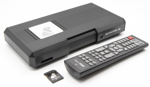
RetroTINK-4K (通称 "TINK-4K" または "RT4K") は RetroTINK LLC によるとても先進的ななビデオスケーラーである。 先行製品である RetroTINK-2X や RetroTINK-5X の機能を元に RetroTINK-4K は4K60までの解像度でハイエンドなビデオスケーリングや映像処理を提供する。 このページは RetroTINK-4K の取扱説明書であると同時に、各機能の最適な使い方を理解するためのハウツーガイドとしての役割がある。
以下は Console Mods での RetroTINK-4K について取り扱うページの一覧表である:
| メインページ | ファームウェア置き場 | システム設定 | SDカードに保存できる事項 |
|---|---|---|---|
| 現在のページ。RT4Kの操作方法や追加ガイド、コミュニティリソース、FAQ/トラブルシューティングなどをカバーしている。 | GitHubから公式リリースされたすべてのRT4Kファームウェアがダウンロードできる。 | RT4Kにゲーム機を初めて接続する際に考慮すべき設定についての説明。 | プロファイル、CRTマスクプロファイル、カラーコレクションプロファイルついてなど、SDカードに保存できる事項についての説明。 |
概要
RetroTINK-4Kは、ビデオラインダブラーとアップスケーラーのRetroTINKの最新の進化形である。ケースの寸法を含む回路図については CAD and Schematics アーカイブを参照。
以下は主な特長のリストである:
出力
- HDMI® 最大4K60
- さまざまなリフレッシュレートで480p, 1080p, 1440pを含む柔軟な出力モード
- SDカード上のCustom modelines
- Triple Buffer:完全に映像をバッファリングしたモード(入力切替時の暗転なし)および Gen Locked と Frame Locked の3つの同期モード
- Rec.2020にフルカラー補正されたHDR10出力
- 高フレームレートモード: 1440p120, 1080p240
- ディープカラー出力オプション (4K60での10bitは全てのディスプレイで互換性があるわけではない)
- 最大8チャンネルLPCMオーディオ
入力
- ほぼすべてのアナログフォーマットに対応
- ミニD-sub15ピン(HD15)/VGA: RGBHV, RGBS, RGsB, YPbPr, S端子およびコンポジットビデオ
- SCART: RGBS, RGsB, YPbPr, S端子およびコンポジットビデオ
- 背面RCA: RGsB, YPbPr(コンポーネントビデオ/D端子(要変換))およびコンポジットビデオ
- 前面 コンポジットビデオ
- 前面 S端子
- HDMI® 入力 最大1080p60/1200p(CVT-rb)、最大8チャンネルLPCMに対応
- 最大96kHz/24ビット・サンプリングのアナログ・オーディオ入力(ゲイン調節可能)
- 2チャンネルLPCMまたは圧縮サラウンド対応の光TOSLINKオーディオ入力
- HDMI® オーディオ は最大8チャンネルのLPCMに対応
アナログ映像処理
- Gain(明るさ)の自動調整
- Phase(位相)の自動調整
- 入力映像の自動クロッピングによる縁取り
- 明るさ、オフセット、サンプル・レートのフルコントロール
- ゲーム機固有の自動サンプルレート検出(実験的機能)
- 規格外な映像出力仕様のアーケード基板やOld PCにも対応(映像を適切にトリミングし、中央に配置するためにカスタム・プロファイルが必要になる場合がある)
- 最大入力解像度 1920x1080p60 または 1920x1200p60 CVT-rb
- マルチリージョン(NTSC、PAL、PAL-60、SECAM)に対応した堅牢なコンポジット/S端子ビデオデコーダー
スケーリング
- 他の設定とは独立して水平および垂直スペースで完全に柔軟なカスタムクロッピングとズームが可能
- 4:3または16:9への自動アスペクト比補正
- 逆テレシネ用の3:2および2:2でのフィルム・モードを含むMotion Adaptiveインターレース解除(実験的機能)
- 時計回りまたは反時計回りいずれでも縦画面ゲーム用の90度回転可能 (入力: 240p, 288p および 360p 時)
疑似CRT
- 複数のCRT電子ビームのプロファイル
- 完全に設定可能なCRT電子ビーム強度と強度調整
- 調整可能なCRTマスクと強度
- オフセットスキャンラインによる疑似インターレース映像
- 非整数倍のスケーリングにも自動的に適応するLCDシミュレーションパターン
映像処理
- エンド・トゥ・エンドで内部12bit精度のRGBパイプライン
- 従来のガンマ・モードと量子化誤差を最小化する近似モード
- 高度で完全に設定可能なガンマと知覚量子化器(HDR)
- 異なるディスプレイ技術をシミュレートする高度な色域変換
- パターンと強度をカスタマイズできるBFI挿入エンジン
- リニアライト処理
ユーザーインターフェース
- 高度なOSDメニューシステム
- カスタムモデル、ファームウェア更新、プロファイル保存用SDカード
- 100,000以上のプロファイルをサポート
- カスタム・プレミアム・リモートコントロール
製品内容
新品のRetroTINK-4Kのパッケージには以下のものが付属する:
- RetroTINK-4K本体 x1
- 8GB SDカード, ソフトウェアとプロファイルがインストール済み x1
- USB-A / USB-C SDカードリーダー x1
- リモートコントロール x1
- USB-A to USB-C 電源コード x1
| パッケージにはACアダプターやHDMI®ケーブルは含まれていない。電源には最近の携帯電話の充電器に同梱されているような5V 2A USB-Aアダプターの使用を推奨する。RT4KをディスプレイのUSBポートに接続することは推奨しない。HDMI®については、18Gbps以上のHDMI®2.0以上のケーブルであればRT4Kで動作する。信頼できる業者から製品を購入して欲しい。 |
はじめる
RetroTINK-4Kはパワフルでありながら使いやすく、素早くセットアップできるように設計されている。RetroTINK-4Kを使い始めるための手順は以下の通り:
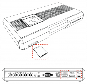
- SDカード - RetroTINK-4Kにはファームウェアとプロファイルを含むSDカードが同梱されており、RT4Kの動作にはこのSDカードが必要なので挿入されていることを確認する。SDカードを紛失した場合、またはSDカードに問題がある場合はFAT32でフォーマットされたSDカードまたはアダプター付きmicroSDカードで代用できる。以降のリンク先のツールでフォーマットされた1TBまでのカードがテストされている this tool.
- USB-C電源 - 少なくとも5V/2Aを供給するUSB-CケーブルをRT4KのUSB-C電源入力に接続する。
- 映像出力 - RetroTINK-4Kの出力端子からHDMI®ケーブル(2.0以上/18Gbps+)をディスプレイに接続する。
- 映像入力 - RetroTINK-4Kの 入力のいずれかに(ゲーム機、PCなどの)デバイスの出力を接続する。 サポートされている接続の詳細は 入力 セクション参照。
- 映像出力確認 - RetroTINK-4Kはデフォルトだと4K60で出力する。もし映像が表示されない場合はディスプレイが4K60に対応していることを確認するか、ディスプレイの解像度 (1080p, 1440p または 480p)に合ったリモコンのボタンを押して対応する。詳しくは リモコン と 出力 セクションを参照。
- 入力ソースの選択 - リモコン上部にある "Input" ボタンを押し、ゲーム用機器を接続しているポートと信号を選択する。
- 楽しむ - ソース映像が見えたらRetroTINK-4Kの高画質、低遅延スケーリングを楽しむ準備が完了している。ゲームをプレイする時間だ!
基本的なアナログ調整
ゲームを実行している場合およびアナログ映像入力を使用している場合、次の2ステップを検討することを推奨する (備考 HDMI® 映像入力時は以下の調整は不要):
Gain(明るさ)の自動調整 - RetroTINK-4Kには自動的にゲインを調整する機能があり、画面のどこかに真っ白な部分がある限りうまく機能する。ゲインは機器ごとに設定する必要がある。
上級者はAdvanced Settingsの手動明るさ調整(manual gain control)を使用してもよい > RGB/Component ADC, 240p Test Suite と合わせて。 | |
|
|
映像のクロッピング - 画像のクロッピングとはRetroTINK-4Kが映像をスクリーンの端に合わせてスケーリングし、中央に配置することである。最良の結果を得るには、(境がわかるよう)黒や暗いエッジのない画面を使用する。クロップはゲームごとに適用する必要がある。
映像のクロッピングやサイズ変更は Advanced Controls > Scaling/Cropping から手動でおこなうこともできる。詳しくは左記リンク先セクション参照で。 |
微調整、フィルター、そしてその先へ
もちろんRetroTINK-4Kでできることはまだまだたくさんある。ここでは、さらに高度なオプションをいくつか紹介する:
ファームウェア更新
ファームウェアの注意事項やダウンロードについては、 RetroTINK-4K Firmware GitHub を参照。
ファームウェアのインストール
RetroTINK-4Kはどのファームウェア(古いファームウェアを含む)にもアップデート可能で、新しいリリースではさらなる新機能が追加される。
- RetroTINK-4Kの電源を落とした状態でSDカードを抜く。
- RT4Kで使用するSDカードをパソコンのSDカードスロットに挿入する。パソコンにSDカードスロットがない場合は付属のUSBアダプターを使用する。
- RetroTINK firmware websiteからファームウェアのZIPファイルをダウンロードする。
- ZIPファイルの中身(".rbf"と"rt4kup.bin" ファイル)をSDカードのルートディレクトリに展開する。SDカード上の既存の "rt4kup.bin "ファイルはインストールするファームウェアを決定するのに使用されるため、必ず置き換えること。
- RT4Kのメニューから更新する場合、古い *.rbf ファイルを削除しないように。 もし現在使用しているrbfファイルを削除するとリセットボタンを使用した更新を余儀なくされる(この方法については以下Step 6参照)。
- PCからSDカードを取り出し、RetroTINK-4KのSDカードスロットに挿入する。
- ファームウェアのインストールには二通りの方法がある。RT4Kは "rt4kup.bin" ファイルをもとにファームウェアをインストールする。
- 選択肢 1: RetroTINK-4Kの電源を入れ、Advanced Settings > OSD/Firmware に進める。"Firmware Update" セクションで "Check SD Card" を選択し、ファームウェアファイルをスキャンしたあと、インストール確認ダイアログでOKを選択する。
- 選択肢 2: RetroTINK-4Kの背面にある青いリセットボタンを押しながら電源オンすると自動的にファームウェアのインストールが始まる。
- LEDが赤く点滅している場合、インストールエラーが発生している。SDカード上のファイルを確認してから再実行すればよい。
- RT4Kは約40秒間で再起動し、前面のLEDがピンクから青に点滅する。再起動が完了すると緑色のLEDが点灯し、通常通り電源が入る。これにて完了!
| RT4Kの電源が入らない、またはLEDが黄色に点滅する場合はSDカードから現在の.rbfファームウェアファイルが消去されている。.rbfファイルと.binファイルの両方がSDカードのルートにあることを確認し、上記のリセットボタンを使用する。 |
カスタムプロファイル、CSCファイル、バナー画像、入力モード、マスクオーバーレイ、modelinesはRT4K本体ではなくSDカードに保存されるため、ファームウェアを更新してもすべて保持される。
重要な新機能
RetroTINK-4Kを入手した人のために発売後に追加された主な機能を紹介する。
- MiSTer DV1のサポートにより、MiSTerコアからの映像出力を自動decimatingおよび自動クロッピング。
- セガサターンのオートサンプリング対応。
- 3:2および2:2テレシネ・デインターレーサーを書き換え、安定性と応答時間を改善した。
- HDMI® 入力ソース時の自動クロッピング。
- プログレッシブソースにインターレーススキャンラインを追加できるようになった。
- Atomosレコーダーにおける音声の不具合や、AVR経由でのHDR infoFrameの欠落など、HDMIオーディオの互換性に関するさまざまな問題を修正。
リモートコントローラー(リモコン)
| RetroTINK-4K Remote Diagram | |||||||||||
|---|---|---|---|---|---|---|---|---|---|---|---|
| ボタン | 説明 | IRコード | ボタン | 説明 | IRコード | ボタン | Description | IRコード | |||
| Power | Powers on / off the RT4K | 0xE51AB649 | 11 | Profile 11 | 0xD926B649 | 4K | Switches to 3840x2160p 60Hz | 0xCF30B649 | |||
| INPUT | Input source selection menu | 0xEE11B649 | 12 | Profile 12 | 0xD827B649 | 1080p | Switches to 1920x1080p 60Hz | 0xCE31B649 | |||
| OUT | HDMI® Output menu | 0xDF20B649 | MENU | RetroTINK-4K Main Menu | 0xA35CB649 | 1440p | Switches to 2560x1440p 60Hz | 0xCD32B649 | |||
| SCL | Scaling/Cropping menu | 0xDE21B649 | BACK | Back out to previous menu | 0xBD42B649 | 480p | Switches to 720x480p 60Hz | 0xCC33B649 | |||
| SFX | Processing/Effects menu | 0xDD22B649 | △ | Up | 0xE718B649 | RES1 | Custom Output Resolution 1-4.
See Custom Modelines for further explanation. |
0xCB34B649 | |||
| ADC | HDMI® Receiver menu HDMI® In が表示されている場合
RGB/Component ADC menu RGB or Component input が表示されている場合 SDP Decoder menu Composite / S-Video input が表示されている場合 |
0xDC23B649 | ◁ | Left | 0xA857B649 | RES2 | 0xCA35B649 | ||||
| PROF | Profiles menu | 0xDB24B649 | ENTER | Enter | 0xAC53B649 | RES3 | 0xC936B649 | ||||
| 1 | Profile 1 | 0xF40BB649 | ▷ | Right | 0xB04FB649 | RES4 | 0xC837B649 | ||||
| 2 | Profile 2 | 0xF807B649 | ▽ | Down | 0xEF10B649 | AUX1 | "Vertical Only" Auto Crop | 0xC738B649 | |||
| 3 | Profile 3 | 0xFC03B649 | DIAG | Diagnostic Console screen | 0xD728B649 | AUX2 | "Full Crop to 4 by 3" Auto Crop | 0xC639B649 | |||
| 4 | Profile 4 | 0xF50AB649 | STAT | Status screen | 0xD629B649 | AUX3 | "Full Crop to 16 by 9" Auto Crop | 0xC53AB649 | |||
| 5 | Profile 5 | 0xF906B649 | AUTO-GAIN | Auto Calibrate Gain | 0xD42BB649 | AUX4 | 0xC43BB649 | ||||
| 6 | Profile 6 | 0xFD02B649 | AUTO-PHASE | Auto Calibrate Phase | 0xD22DB649 | AUX5 | 0xC33CB649 | ||||
| 7 | Profile 7 | 0xF609B649 | PLAY/PAUSE | Pause current screen | 0xA956B649 | AUX6 | 0xC23DB649 | ||||
| 8 | Profile 8 | 0xFA05B649 | SAFE | Safe Mode | 0xD12EB649 | AUX7 | 0xC13EB649 | ||||
| 9 | Profile 9 | 0xFE01B649 | SYNC-GEN | Sync Lock - Gen Lock | 0xD32CB649 | AUX8 | 0xC03FB649 | ||||
| 10 | Profile 10 | 0xDA25B649 | SYNC-BUF | Sync Lock - Triple Buffer | 0xD02FB649 | - | |||||
IRコードはCharlieBeatnik提供。
Raw IR Code 0xE51AB649 (NEC protocol) corresponds to address 0x49, command 0x1A.
一時停止ボタン(Pause Button)
リモートには他ではアクセスできない機能が1つある。これを押すと現在のフレームが一時停止し、音声がミュートされる。このフレームは別の入力ソースに切り替えても記憶される。
- おそらく一時停止ボタンの最も便利なアプリケーションは Deinterlacer/Film メニューである。 ここではデインターレース設定を調整してその効果を動いているシーンでより簡単に見ることができ、より簡単に好みに調整することができる。
| 別のプロファイルをロードしたりクロップツールを使用したり、3:2逆テレシネを使用したりする場合など、一時停止機能を使用すると望ましくない結果になる状況がいくつかある。また、Black Frame Insertion 機能は新しいビデオフレームを必要とするため、まったく表示されなくなる。このような場合は一時停止を解除して通常の操作を再開すればよい。 |
セーフモード(Safe Mode)
セーフモードは本体背面の青いリセットボタンを押すか、リモコンの "SAFE"ボタンを2秒間押し続けることでアクセスできるオプションである。これにより以下のことが起こる:
- デフォルトプロファイルのロード。
- 入力モードがHDMI® に。
- 出力モードが480p 59.94 Hzに。
セーフモードはトラブルシューティングに使用するためのものである(HDMI®をサポートするディスプレイは480p60をサポートしているため)。また、なんらかの理由でRetroTINK-4Kをデフォルトの状態に戻す必要がある場合にも便利である。
LEDライト
RetroTINK-4Kは前面のLEDライトの色と動作を変化させ、ユーザーに動作に関する情報を伝える。以下はLEDライトの動作とその意味を示す。
| 色 | 説明 |
|---|---|
| 消灯 | RT4Kの電源が落ちている状態。 |
| 赤色のゆっくりとした点滅 | RT4Kがスリープしている状態。使用するには電源オンが必要。 |
| 白色 | RT4Kが起動中。まだ使用はできない。 |
| 緑色 | RT4Kが使用可能な状態。 |
| 黄色に点灯 | 起動中にSDカードにシステムファイルが見つからない。SDカードが正しく挿入されているか.rbfシステムファイルがあるかrt4kup.binファイルが一致するかを確認する。 |
| 紫-紫点滅 | RT4Kがファームウェア更新中。 |
| 青-青点滅 | ファームウェア更新成功。 |
| 赤点滅 | ファームウェア更新エラー。SDカードのファイルを確認し、再試行する(本体が壊れているわけではない)。 |
入力(Inputs)
RetroTINK-4Kは Input Selection メニューで選択できる様々な信号とコネクタタイプの入力を備えている。これらのオプションにはリモコン上部の入力ボタンを押すか、メニューボタンを押して "Input Selection" を選択することでアクセスできる。
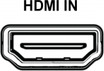
HDMI®
| RetroTINK-4Kは1920x1080p60または1920x1200p60 CVT-rbまでの多くの解像度をデジタルでサポートする。標準的な民生品とは異なり、RetroTINK-4Kは任意の解像度や規格外の解像度を許容し、適応することができる。
なお、1440p および 4K入力には非対応。もしこれらがRT4Kに入力された場合、何も表示されない。 |
前面(Front)
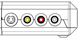
RetroTINK-4Kは前面にS端子(ミニDIN)入力とコンポジット(RCA)入力を備えている(スライドパネルを動かすことで隠したり出したりできる)。赤と白のRCAジャックはステレオ音声入力。赤/白のフロント音声入力は、フロントコンポジットまたはS端子入力のいずれかが選択されているときに有効になる(音声入力の上書き機能が使用されていないと仮定)。
| Front Inputs | ||
|---|---|---|
|
コンポジットビデオ | コンポジットビデオを使用する場合は、ビデオ(CVBS/コンポジット)用に黄色のRCAジャック、左右の音声入力用にそれぞれ白と赤のRCAジャックを使用する。 |
| S端子 | S端子を使用する場合は、ミニDinプラグを映像(Y/C S端子)に、白と赤のRCA端子をそれぞれ左右の音声入力に使用する。 | |
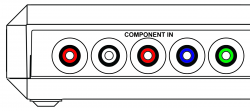
背面のRCA(Rear RCA)
背面のRCA端子は、YPbPr(コンポーネント)、RGsB、CVBS(コンポジットビデオ)の入力に対応している。
| Rear RCA Input | ||
|---|---|---|
| YPbPr(コンポーネントビデオ) | 背面RCA入力はYPbPr(コンポーネントビデオ)をサポートする。最大解像度は1920x1080p、60fps、148.5Mhz。
| |
| RGsB(Sync on Green) | 背面RCA入力はGreen信号と一緒に同期を送るRGBの一種であるRGsB(別名RGB Sync on Green)にも対応している。サポートされる最大解像度は1920x1080p 60fps、または148.5Mhz。
| |
| コンポジットビデオ(緑端子接続) | コンポジットビデオ(CVBS)は背面RCA入力で使用できる。最大対応解像度は480i。
| |
SCART
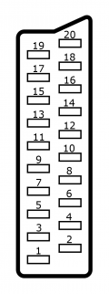
SCARTポートはデバイスの右側にある大きな長方形の入力である。SCARTは1本のケーブルでさまざまなビデオ入力ができるように設計されているため、同じコネクターデザインを使用したさまざまなビデオ入力オプションがある。
| 2つのM4x0.7 ネジ穴がSCARTポートの両側にあり、その中心に対して互いに70.4mm離れている。これらは(HD-15ポートのネジ穴と同様に)SCARTケーブルをより確実にフィットさせるユーザーメイドの解決策を可能にする。 |
| SCART入力 | ||
|---|---|---|
| RGBS (75 ohm) | RGBSはRGBの一種で、同期信号が個別のラインを通して送られる。RetroTINK-4KはSCART経由で以下のRGBS信号フォーマットに対応している:複合同期(CSync)(減衰)、Sync on Luma(S端子の同期)、Sync on Composite(CVBS)。これらはすべて、赤、緑、青、および "Sync"ラインに情報を送信することで動作する。サポートされる最大解像度は1920x1080p 60fps、または148.5MHz。 | |
| RGsB | RGsBは3本のケーブルだけで緑に同期を送る。この RGBフォーマットは、プレイステーション2がSCART 経由で480pモードを使用する場合に特に使用される。サポートされる最大解像度は1920x1080p 60fps、または148.5MHz。 | |
| YPbPr | YPbPr is sent through the Green, Blue, and Red pins, respectively. The maximum resolution supported is 1920x1080p 60fps, or 148.5 MHz | |
| CVBS on Pin 20 | Composite video sent through Pin 20, usually through a composite to SCART adapter or if your cable uses sync-on-composite video and you wish to use composite instead of RGB. As with all composite signals, only 240p/480i/288p/576i signals are supported. | |
| CVBS on Green | Composite video can be sent through the Green pin. This would be useful if you use a component (YPbPr) to SCART adapter, just plug composite (yellow) into the Y RCA jack (Green). As with all composite signals, only 240p/480i/288p/576i signals are supported. | |
| Y/C on Pin 20/Red | S-Video (Y/C) can be sent down Pin 20 (sync) and the Red pins. You will need a S-Video to SCART adapter. As with all S-video signals, only 240p/480i/288p/576i signals are supported. | |
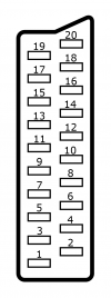
| SCART端子配列 | |||||||
|---|---|---|---|---|---|---|---|
| Pin # | RGBS (75 Ohm) | RGsB | YPbPr | CVBS on Pin 20 | CVBS on Green | Y/C on Pin 20/Red | |
| 1 | Unused | ||||||
| 2 | Audio In - Right | ||||||
| 3 | Unused | ||||||
| 4 | Ground | ||||||
| 5 | Ground | ||||||
| 6 | Audio In - Left | ||||||
| 7 | Blue | Blue | Pb | ||||
| 8 | Unused | ||||||
| 9 | Ground | ||||||
| 10 | Unused | ||||||
| 11 | Green | Green+Sync | Y | CVBS | |||
| 12 | Unused | ||||||
| 13 | Ground | ||||||
| 14 | Unused | ||||||
| 15 | Red | Red | Pr | Chroma (C) | |||
| 16 | Unused | ||||||
| 17 | Ground | ||||||
| 18 | Ground | ||||||
| 19 | Unused | ||||||
| 20 | Sync | CVBS | Luma (Y) | ||||
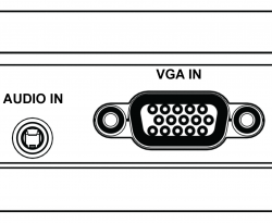
ミニD-sub15ピン(HD-15)
ミニD-sub15ピン (HD-15/VGAコネクター) は一般的にPCで使用されていたが、セガ ドリームキャストでも使用できることで有名である。
| SCARTと異なり、HD-15ポートは音声を受け付けない。HD-15を使用する場合、音声はRT4Kの3.5mmステレオミニジャックまたはトスリンクで "optical" 入力を使用する。 |
| ミニD-sub15ピン(HD-15)入力 | ||
|---|---|---|
| RGBHV | RGBHVはRGBの一種で5本のラインを通して情報が送られる: 赤、緑、青、水平同期、垂直同期。サポートされる最大解像度は1920x1080p 60fps、または148.5MHzである。これはPCソースで最も一般的である。 | |
| RGBS | RGBS は RGB の一種であり、同期は個別のラインを通して送られる。RetroTINK-4KはHD-15経由で以下のRGBS信号フォーマットを受け入れる: 複合同期(CSync)(減衰)、Sync on Luma(S端子の同期)、Sync on Composite(CVBS)です。これらはすべて、赤、緑、青、およびSyncラインに情報を送ることで動作する。サポートされる最大解像度は1920x1080p 60fps、または148.5MHz。 | |
| RGsB | RGsBは3本のケーブルだけで緑に同期を送る。この RGBフォーマットは、プレイステーション2がSCART 経由で480pモードを使用する場合に特に使用される。サポートされる最大解像度は1920x1080p 60fps、または148.5MHz。 | |
| YPbPr | YPbPr is sent through the Green, Blue, and Red pins, respectively. The maximum resolution supported is 1920x1080p 60fps, or 148.5 MHz | |
| CVBS on Hsync | Composite video sent through the horizontal sync line. As with all composite signals, only 240p/480i/288p/576i signals are supported. | |
| CVBS on Green | Composite video can be sent through the Green line. As with all composite signals, only 240p/480i/288p/576i signals are supported. | |
| Y/C on Green/Red | S-Video (Y/C) can be sent down Green (Y) and the Red (C) pins. As with all S-video signals, only 240p/480i/288p/576i signals are supported. | |
| Y/C on G/R (Enc.) | An enhanced S-Video mode only available on the HD15 connector. (Y/C) can be sent down Green (Y) and the Red (C) pins. As with all S-video signals, only 240p/480i/288p/576i signals are supported. Sampling and Luma calibration is done in the RGB/Comp. ADC Setup menu, and settings noted in the system specific settings apply. | |
| ミニD-sub15ピン(HD-15)端子配列 | |||||||||
|---|---|---|---|---|---|---|---|---|---|
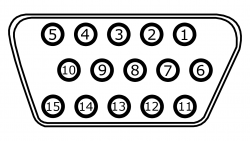
| Pin # | RGBHV | RGBS | RGsB | YPbPr | CVBS on Hsync | CVBS on Green | Y/C on Green/Red & Enhanced Y/C | Data | |
| 1 | Red | Red | Red | Pr | Unused | Chroma(C) | Unused | ||
| 2 | Green | Green | Green+Sync | Y | Unused | CVBS | Luma(Y) | Unused | |
| 3 | Blue | Blue | Blue | Pb | Unused | ||||
| 4 | Unused | ||||||||
| 5 | Ground (Horizontal Sync) | Ground (Sync) | Unused | Ground (CVBS) | Unused | ||||
| 6 | Ground (Red) | Ground (Red) | Ground (Red) | Ground (Pr) | Unused | Ground (Chroma/C) | Unused | ||
| 7 | Ground (Green) | Ground (Green) | Ground (Green+Sync) | Ground (Y) | Unused | Ground (CVBS) | Ground (Luma/Y) | Unused | |
| 8 | Ground (Blue) | Ground (Blue) | Ground (Blue) | Ground (Pb) | Unused | ||||
| 9 | Unused | ||||||||
| 10 | Ground (Vertical Sync) | Unused | |||||||
| 11 | Unused | ||||||||
| 12 | Unused | External Transmit (EXT TX) | |||||||
| 13 | Horizontal Sync | Sync | Unused | CVBS | Unused | ||||
| 14 | Vertical Sync | Unused | |||||||
| 15 | Unused | External Receive (EXT RX) | |||||||
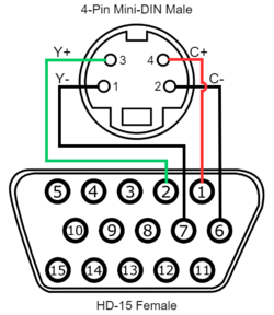
| 拡張S端子接続(Enhanced S-Video Wiring) | |||
|---|---|---|---|
| 信号 | ミニD-sub15ピン(HD-15) (メス) | 4ピン ミニDin (オス) | |
| Luma (Y) Signal | 2 (Green) | 3 | |
| Luma (Y) Ground | 7 (Green Ground) | 1 | |
| Chroma (C) Signal | 1 (Red) | 4 | |
| Chroma (C) Ground | 6 (Red Ground) | 2 | |
3.5mm ミニジャック音声入力(3.5mm TRS Audio)
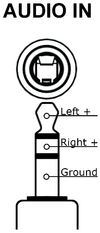
| The RetroTINK-4K allows for audio through a 3.5mm TRS input. This accepts stereo analog audio. By default, this is associated with the HD-15 port, as that port does not accept audio signals. |
光デジタル音声(Optical Audio)
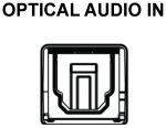
| The RetroTINK-4K offers a discrete optical audio TOSLINK input. This input can accept 2-channel LPCM and compressed surround sound. |
代替音声入力
RetroTINK-4K では、音声入力をデフォルトの映像ソースから再割り当てすることができる。まずAdvanced Settings から "Acquisition" セクションの下にある "Audio Input"を選択する。次にSourceセクションの下にある "Input Override" オプションにより現在入力されている映像入力の音声を別の音声ソースから取り込むことができる。唯一の例外としてHDMI® オーディオを非HDMI® 映像ソースに割り当てることはできない。ただし、その逆は可能。
- このメニューには "入力入れ替え" オプションもあり、オーディオ入力チャンネルを入れ替えたり(サードパーティ製のサターンケーブルを使用する場合に便利)、左右のチャンネルを使ってモノラルオーディオを出力したり(ファミコンのようなシングルチャンネルシステムに便利)できる。
| イラスト | 名称 | 説明 |
|---|---|---|
| RCA (Rear) | The leftmost two RCA inputs in the rear. White and Red, | |
| HD-15 | The 3.5mm TRS input in the rear. | |
| SCART | The SCART input on the side. Audio is fed in through pins 2 and 6. | |
| Front | The red and white RCA inputs in the front of the unit. | |
| S/PDIF | Optical audio fed through a TOSLINK input. |
HDMI® 出力
RetroTINK-4K はHDMI®出力ポートから のみ 出力する。他のポートから映像や音声を出力することはできない。
HDMI®出力メニューでは出力解像度の設定、ブラックフレーム挿入の有効化、カラースペース出力(カラーメトリー)の変更などを行うことができる。 このメニューの機能の内訳は以下の通り:
出力解像度(Output Resolutions)
以下の出力はRetroTINK-4Kでサポートされており、HDMI®出力メニューの一番下にある最初の11の出力解像度オプションとして提供されている。リモコンの各ボタンを押すことで利用可能な解像度も記載されている。どの解像度を使用すればよいかわからない場合は、リモコンのボタンを使ってすぐに試すことができる。
| 解像度 | 説明 | リモコンのボタンに配置されているか |
|---|---|---|
| 4K60 | 4Kディスプレイ(3840x2160p)のデフォルト解像度とフレームレート。
RT4Kのデフォルト解像度 |
Yes |
| 4K50 | PALのゲームおよび24Hzコンテンツ向け。 | No |
| 1080p60 | 1080pディスプレイのデフォルト解像度。 | Yes |
| 1080p50 | Intended for PAL games. and 24Hz content | No |
| 1440p60 | 1440pモニター(2560x1440p)用のデフォルトの解像度とフレームレート。 | Yes |
| 1440p50 | Intended for PAL games and 24Hz content | No |
| 1080p100 | Intended for PAL games and 24Hz content with BFI | No |
| 1440p100 | Intended for PAL games and 24Hz content with BFI | No |
| 1080p120 | BFI付きNTSCコンテンツ向け。 | No |
| 1440p120 | BFI付きNTSCコンテンツ向け。 | No |
| 480p60 | Minimum suggested output resolution for modern displays, aka 720x480p.
Pressing the Reset button on the back of the unit activates this resolution. |
Yes |
| Custom 1 | Custom resolutions loaded from custom[1-4].txt on the SD card.
See Custom Modelines for further explanation |
Yes |
| Custom 2 | Yes | |
| Custom 3 | Yes | |
| Custom 4 | Yes |
| RetroTINK-4Kは、480i、576i、1080iなどのインターレース出力解像度には対応していない。これらの解像度が必要な場合は、RetroTINK-5XやOSSC Proなどの他の機器を試せばよい。 |
HDR
HDRはRetroTINK-4Kが対応するテレビ向けに、より輝度の高い画像を出力するための方法である。HDRは Black Frame Insertion や Scanlines and Masks,と併用することを想定しており、暗くなった画像を補正するのに役立つ。
- 現在選択可能なオプションは "HDR10 [8-bit]" のみ。
- HDRの明るさは Advanced Settings > Color Correction で "SMPTE 2084 PQ" の値で調整可能。これはスキャンラインのないHDRで再生したい場合に便利で、明るすぎるのではなく、明るいトーンが知覚できるようになる。
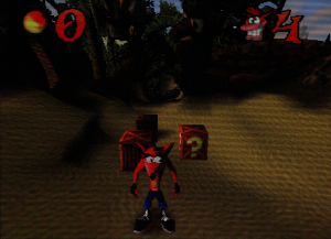
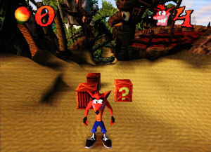
下の表は、HDR CRT Simulationフォルダの下にある "PVM 600 TVL" プロファイルを使用して、LG-CXでRT4Kを表示した2枚の写真である。HDRの輝度をSDRで伝えることは不可能なので、ここではまずHDRの写真用に露出を設定し、SDRの写真と比較して輝度が向上していることを示している。
| PVM 600 TVL scanlines - SDR | PVM 600 TVL scanlines - HDR. |
|---|---|
| HDRは "スキャンライン、マスク、BFIでの使用を意図したもの" である。これらの機能を使用していない場合は、HDRをオフにするのが最善である。画像が暗すぎる場合は、入力の調整 [adc adjustments]、カラーメトリーによる出力色空間の調整(下記参照)、または色補正 [CSC Color Correction] を検討して欲しい。 |
色彩測定(Colorimetry)
HDMI® 出力の色空間を指定する。デフォルトでは、Auto設定は Rec.709 を選択し、HDRが有効な場合は Rec.2100 に切り替わる。使っているディスプレイがより広い色域をサポートしている場合、出力を Rec.2020(HDRを有効にしない)、Adobe RGB、または DCI-P3 に手動で設定することができる。これにより、色補正メニューの設定を使用する際の画質/精度が向上する可能性がある。
RGBレンジ(RGB Range)
HDMI®レンジをフル(既定値)またはリミテッドに設定する。1つの設定が他より優れているわけではないが RT4Kとディスプレイの範囲が一致していることを確認して欲しい。もしディスプレイがリミテッドレンジを使用するのであれば、このオプションをLimitedにすることを検討して欲しい。もしディスプレイがフルレンジを使用できるのであれば、この設定はそのままにしておく。
同期ロック(Sync Lock)
Sync Lockは、RetroTINK-4Kが出力フレームレートを入力フレームレートに同期させ、これらの入力変更を処理する方法を制御する。
古いゲーム機は必ずしも完璧な映像タイミングを持っていたわけではなく、CRTでは通常問題なく動作していたが、このような"不正確な"ゲーム機は、より厳格な規格に準拠した現代のテレビやキャプチャデバイスでは動作するのが難しい場合がある。プレイステーション1の "サイレントヒル" や "クロノ・クロス" など、一部のゲームでは、ゲーム中やアイテム/一時停止メニューで、それぞれ240pまたは480iのビデオモードが交互に切り替わる。多くのディスプレイ、アップスケーラー、キャプチャデバイスでは、デバイスが別の映像モードに再調整される間、長い遅延と "No Input" 画面が数秒間表示される。映像モード間の変更にゲームプレイに支障をきたすほどの時間がかかるデバイスの問題は、俗に「クロノクロス」問題と呼ばれている。RT4Kがこの問題をどのように処理するかは、Sync Lockセクションで選択できる。
- Triple Buffer - 出力を入力から独立して動作させるため入力信号に不具合や変化があっても安定した出力信号が得られる。ただし、その代償として通常は1フレームの数分の1から数分の1+1フレーム分のラグが生じる。同期を維持するためにフレームを落としたり繰り返したりする必要がある場合、画面震えが発生することがある。
- Gen Lock - 映像ソースのリフレッシュレートにディスプレイの互換性がある限り、このモードが推奨される。Gen Lockは、出力フレームレートを入力フレームレートにルーズに結合する。数秒後、出力フレームレートは入力フレームレートにロックされ、画面揺れなしで最小のラグを達成する。もしGen Lockに問題があるようなら、VRR を有効にするのを試して欲しい。
- Frame Lock - 入力と出力のフレームレートを密に結合する。入力フレームレートが変わると出力信号が乱れ、再同期が難しくなる。
VRR (Variable Refresh Rate)
RetroTINK-4KはVRRフラグを立てることができる。RetroTINK-4K自体が可変フレームレートを出力することはないが、このフラグを設定することでGen Lockを使用している場合などディスプレイがより広い範囲のリフレッシュレートを受け入れるようにすることができる。また、ディスプレイによっては、RetroTINK-4Kの BFI generator と干渉する再バッファリングやその他のフレームレートの変更を防ぐのにも便利である。最後に、一部のテレビはVRRフラグを検出すると低ラグモードを起動し、ゲームプレイ体験を向上させる。
Deep Color
このオプションはRT4Kのビットカラー深度を 8 ビット (オフ) から 10 ビット (オン) に変更し、画像の色数を増やす。画像の色を調整する設定を使用した場合、これは便利である。
| 4K60出力の使用中にDeep Colorを有効にすると HDMI 2.0の帯域幅仕様を超えるため、テレビやキャプチャ カードなどの一部の機器で問題が発生する可能性がある。この場合、Deep Colorを無効にするか出力解像度を下げるかのいずれかを選択できる。PALシステムでは、HDR が無効になっている限り、代わりに 4K50 オプションを選択するとうまくいく可能性がある。 |
BFI Control
Black Frame挿入のStrobe(ストロボ)とBlur(ぼかし)機能に素早くアクセスできる。これらの機能やその他のBFIコントロールについては、 Black Frame Insertion (BFI) セクションを参照。
音声出力(Audio Output)
サラウンド音声(Surround Sound)
RT4KはHDMI® 経由で最大 8 チャンネルのLPCMを出力する。As of Firmware 1.4.2, and per previous testing all 8 channels are output simultaneously but the channels are correctly routed, so if your receiver reports 7.1 but is only a 5.1 receiver, you should still have correct function from the RT4K.
RT4Kは、Dolby Surround®とDolby Surround®の過去のすべてのバージョンも通過する。これはサラウンド音声をステレオ信号でエンコードするため、この信号からサラウンド音声をデコードするかどうかはすべてレシーバー次第である。
プロファイル(Profiles)
| すべてのオプションは1つのプロファイルに保存される。新しいプロファイルをロードする場合、切り替える前に変更した設定を保存していないとすべての設定変更が失われる。これは、入力設定、出力解像度、スキャンライン設定を含むすべての項目が該当する。比較のためにプロファイルを切り替える前に、プロファイルの設定を保存することを検討して欲しい。 |
Profilesセクションは、SDカードに用意されているすべてのプロファイルと自分で設定したプロファイルを扱う。プロファイルでは設定を保存して後で読み込むことができる。CRTプリセットも保存されたプロファイルなのでここで扱う。
- デフォルトでSDカードに提供されるプロファイルのリストについては、 Profiles breakout page を参照。
- デフォルトでSDカードに提供されていない、コミュニティによって作られたプロファイルのコレクションについては Community Profiles セクションを参照。
プロファイルの読み込み(Load Profile)
- Load From File - これを選択するとメニューが表示され、SDカード上の "profile" フォルダをナビゲートして特定のプロファイルをロードすることができる。
- Load Default - デフォルトプロファイルをロードする。デフォルトプロファイルは削除したり上書きしたりすることはできない。
"Load From File" メニューのプロファイルの配置は、SD カードの "profile" フォルダの物理ファイル構造と一致する。つまり、デフォルトのレイアウトが気に入らない場合はフォルダ構造を好みに合わせて変更すればよい。
プロファイルの保存(Save Profile)
- Save Current - 現在ロードされているプロファイルを現在の設定で上書きする。Default Profile を使用しているときに選択すると "Save As New" と同様の動作をする。
- Save As New - 現在のプロファイルを 「New Profile X」 という名前の新しいファイルとして保存する。このファイルはSDカードの "profile"フォルダに保存され、PCを使って名前を変更することができる。
プロファイルの割り当て(Assign Profile)
このセクションでは "Load From File" 機能と同じSDカードナビゲーションメニューを使用して、リモコン上部の12個の数字ボタンの1つを特定のプロファイルに割り当てることができる。
さらに、ここでRetroTINK-4Kの電源投入時にロードするプロファイルを割り当てることができる。これはデフォルトプロファイルではない。
割り当てられたプロファイルは編集したいボタンをハイライトし、リモコンの◁(左)を押すことでクリアできる。
スケーリングとクロッピング(Scaling and Cropping)
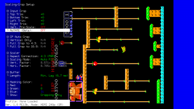
Scaling / Crop Setupメニューでは、画像のクロッピングとリサイズをおこなう。RetroTINK-5Xとは異なり、RT4Kはデフォルトではクロップに基づいて画像のサイズと位置を決めるが、Scaling Mode の設定で上書きすることができる。
Input Crop
RetroTINK-4Kはサイズ、位置、クロッピングを調整するための強力なコントロールを備えている:
- "Top Trim"と "Bottom Trim" ほとんどのScaling Modesで効果的に画像を上下に拡大縮小する
- Top/Bottom Trimsのエッジをより見やすくするには、スケーリングモードを "Auto Fill Integer" に設定する。
- RT4Kは "Left Trim"と"Right Trim" の設定に基づいて画像を自動的に中央に配置する。
- 画像を左右にシフトするには、左または右のトリムを増やして画像を反対方向に押し出す。
Vertical Pre-Scale
The RetroTINK-4K features the ability to "Pre-Scale" video content, or discard scanlines, at a fractional increment of the source input. Discarding vertical lines results in a loss of vertical resolution. This loss can be useful under certain circumstances, such as creating more accurate scanline rendering for 240p visual content output from consoles that run at higher resolutions (such as the Dreamcast or Wii).
縦回転(RoTATE)
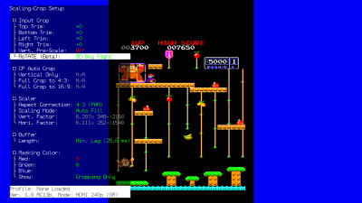
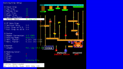
RoTATE (pronounced "roh-tah-tay") is a special feature within the RetroTINK-4K to rotate the image 90 degrees clockwise (right) or counterclockwise (left). This is especially useful for games that may only display their image horizontally, such as many arcade shooters.
| 縦回転(RoTATE)例 | ||
|---|---|---|
| 標準出力 | 右90度(90 Degrees Right) | 左90度(90 Degrees Left) |
The RoTATE mode will only work if the samples per line of your video source is lower than 1024 samples per line (visible in the RGB/Component ADC menu).
- コンポジットビデオとS端子の映像は1ラインあたり858サンプルにロックされているため、これらの入力ソースを使用する場合、追加の微調整は必要ない。
- さらに、縦回転(RoTATE)モードは240p、288p、360pの解像度でのみ動作する。これは480iと混在するタイトルでは重要である。
If you're using RGB or YPbPr input, visit the RGB/Component ADC section of this page for information on ADC and decimation settings to meet the 1024 samples per line requirement. Similar limits apply when using HDMI® sources: use the Input Decimation settings in the "HDMI® Receiver" menu if the horizontal samples exceed 1024 (for example, MiSTer cores that use pixel repetition).
自動クロップ(Auto Crop)
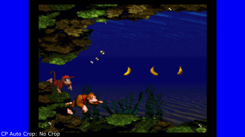
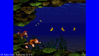
RetroTINK-4Kは十分なゲーム画面が供給されると入力を自動的に切り取ってアスペクト比を設定できる。この機能は、RGB、コンポーネント(YPbPr)、および HDMI™ ソースで動作する。自動クロップはゲーム画像の黒いエッジを探して切り取るので、最良の結果を得るには、ビデオのエッジがはっきりと見える画像を使用する。
| 暗いエッジのある画面、レターボックス、ピラーボックス、ウィンドウボックスの画面は自動クロッピングで画像のエッジであると誤認され、誤ったクロッピングが行われるため、推奨されない。 |
| Name | Remote Button | Effect |
|---|---|---|
| Vertical Only | AUX 1 | ゲーム画像の上部と下部に "上部トリム" と"下部トリム" を自動的に調整する。左トリムや右トリムは調整されず、アスペクト補正も変更されない。 |
| Full Crop to 4:3 | AUX 2 | 画像の左、右、上、下のトリムを自動的に調整し、アスペクト比を "4:3 (PAR)" に変更する。 |
| Full Crop to 16:9 | AUX 3 | 画像の左、右、上、下のトリムを自動的に調整し、アスペクト比を "16:9 (PAR)" に変更する。 |
Scaler
RetroTINK-4Kのスケーラー セクションには、画像のジオメトリを操作をできるツールがある。
アスペクト補正(Aspect Correction)
アスペクト補正設定では、画像の Pixel Aspect Ratio、または "PAR" を選択する。これは、ゲームが表示されると想定されるディスプレイのアスペクト比 (Display Aspect Ratio、または "DAR"と呼ばれる) と一致する必要があるため重要である。
The Aspect Correction controls are only available when the current Input (analog or HDMI®) is a resolution with a variable PAR factor, such as 240p, 288p, 480i/p, and 576i/p. Most other resolutions will lock the Aspect Correction setting to their expected PAR, no matter the input. For example, 720p over the PS3's Component cables will lock Aspect Correction to "1:1 (Sq. Pixel)", while 480p over PS3's HDMI® cables will let you choose yourself.
|
利用可能なオプションは次のとおり:
| Pixel Aspect Ratio | Description | Display Aspect Ratio Use-Case |
|---|---|---|
| 4:3 (PAR) | Uses the common 4:3 Pixel Aspect Ratio, displaying the pixels slightly wider than squares. | Pre-HDMI® video game consoles, which expect to be displayed on the 4:3 DAR of CRT televisions. |
| 16:9 (PAR) | Uses the 16:9 Pixel Aspect Ratio, displaying the pixels even wider than 4:3 (PAR). | Pre-HDMI® games and systems that offer widescreen modes, such as with the PS2 and the Wii. |
| 1:1 (Sq. Pixel) | Uses the 1:1 Pixel Aspect Ratio, displaying the pixels as perfect squares. | Games and consoles that expect a 1:1 PAR but still output a sub-HD signal, such as PSP, and Game Boy games via the Super Game Boy or Game Boy Player. |
複数のピクセル アスペクト比を使用できるデバイスを使用している場合、ゲームがディスプレイに表示されたときに正しく表示されるようにそのデバイスをRT4Kと正しく適合するように設定することが重要である。
スケーリングモード(Scaling Mode)
スケーリングモードでは自動スケーリングモードを選択したり、手動スケーリングのアスペクト比制約を変更したりできる:
- Auto Fill - 選択したアスペクト補正のアスペクト比に基づいて画面を埋める。
- Proportional - アスペクト補正で選択したアスペクト比を維持するために水平係数を自動的に調整しながら垂直係数を調整できる。
- Free-Form - Untethers the Vertical Factor and Horizontal Factor to allow values outside of the Aspect Correction setting. This setting lets you use the Vert. Factor and Hori. Factor settings to freely transform the image, like on the RetroTINK-5X.
- Auto Fill Integer - Scales the Vertical Factor and Horizontal Factor to the highest possible integer value without exceeding the screen boundaries, while also respecting the ratio selected in Aspect Correction. We highly recommend using the cropping tools to ensure the picture can be as large as possible while using this scaling mode.
このスケーリングモードを使用しているときに画像を可能な限り大きくするには、 cropping tools を使用することを推奨する。
Scaling Factors (Transform Tools)
Horizontal Factor と Vertical Factor により画像を水平方向または垂直方向に伸縮および変換できる。各係数には、それぞれ乗数値、入力解像度、および出力解像度が表示される。
どれが使用可能かは、Scaling Mode がどのオプションに設定されているかによって異なる。Proportionalでは垂直係数がロック解除され、Free-Formでは垂直係数と水平係数の両方がロック解除される。
この関数は簡単な式で表すことができる: [Input Resolution] X [Multiplier] = [Output Resolution].
| Horizontal and Vertical Factor例 | |||
|---|---|---|---|
| Axis | Multiplier | Input Res. | Output Res. |
| Vert. Factor | 9.000 | 240 | 2160 |
| Hori. Factor | 2.045 | 1440 | 2945 |
Buffer
RetroTINK-4K では画面に出力する前にバッファするビデオの量を設定できる。バッファは Sync Lock モードと連動して、全体的な遅延を決定する主な要因となる。
- Min. Lag - バッファを最低限のビデオライン数のみ保存するように設定する。このオプションにより、レイテンシが最小になる。
- 1/2 Frame - 常にフレームの半分をバッファリングする。
- 1 Frame - 常にフレーム全体をバッファリングする。
Min. Lagは通常は互換性があるが、画面ティアリングが発生する特殊なケースに遭遇した場合は、これを「1/2 Frame」または「1 Frame」に設定してみればよい。
| 逆テレシネなどの特定のムービーモードでは、RetroTINK-4K が自動的にフル フレームをバッファリングする。 |
マスキングカラー(Masking Color)
マスキング・カラーの設定では "Scaling/Crop" メニューに表示されるマスクの色を調整できる。デフォルトでは赤0、緑0、青31である。また、マスキングカラーをクロップメニューにのみ表示するか、常に表示するか(RT4Kメニューが表示されていない場合でも)を変更できる。
処理とエフェクト(Processing and Effects)
処理とエフェクトのセットアップメニューでは、ピクセル補間を調整したり、スキャンラインやCRTマスクを追加したりできる。
スキャンラインプリセットはどこにあるか?
RetroTINK-5Xをいつも使っている人なら、このメニューに入ってプリセットがないことに驚くかもしれない。これはSDカードにプロファイルとして保存されているから。
- 同梱のCRTプリセットを読み込むには、メインメニューからProfiles > Load from File > HDR CRT Simulationと進み、使いたいものを選ぶ。
CRTプリセットをプロファイルとして "バンドル" することは、RetroTINK-5X のユーザーにとっては奇妙に思えるかもしれない (CRTプリセットは最適なサンプリング プロファイルに簡単に適用できる)。ただし、最終結果にはあまり影響しない。CRTディスプレイは、美観上本質的に少しぼやけている (PVM や BVM であっても)、そのため、汎用サンプリングを使用することはまったく問題ない。デジタルソースを使用していて、それをデシメーションしている場合 (Nintendo Switch Online や HDMI® 改造システムなど)、Horizontal Interpolation Kernel や Horizontal Blur 機能を使用してぼかしをシミュレートすることを推奨する。
上記の唯一の例外は、LCD スキャンラインを使用している場合である。画像を一定の数値 (4.000 倍や 5.000 倍など) で拡大しないと、各ピクセルを分割する細い線が正しく表示されない。
補間(Interpolation)
垂直カーネルと水平カーネル(Vertical and Horizontal Kernel)
映像処理に関連する補間は、入力に与えられた視覚情報をより多く出力に作り出す技術である。これらの処理は、より視覚的にまとまりのある画像を作成するのに役立ち、画像がスクロールしているときの揺らぎなどの効果を低減する。RetroTINK-4Kは、垂直軸と水平軸に独立して適用できる補間オプションを提供している。
- Bilinear Sharp - The image is scaled up the maximum integer factor that is within the output size using Nearest Neighbor followed by a bilinear scale to the final output size. This option provides sharp pixels without shimmer at non-integer scaling factors.
- Bilinear Medium - The image is scaled up to the closest integer that is smaller or equal to the output pixels divided by 2 using Nearest Neighbor followed by a bilinear scale to the final output size. This option is somewhat softer than Bilinear Sharp but still sharper than regular Bilinear.
- Bilinear Std - The image is scaled using conventional bilinear filtering.
- Bilinear Soft - This performs linear interpolation over 4 pixels instead of the standard 2 pixels resulting in a very soft image. This may be desirable to produce horizontal blur for CRT effects
- Cubic - Interpolation using the bicubic spline kernel which outputs an image sharper than bilinear but softer than Lanczos.
- Lanczos2 and Lanczos3 - Interpolation using the Lanczos family of scaling algorithms. Lanczos is a popular algorithm that provides good results for natural imagery (i.e. movies) and most 3D games.
- None - The image is scaled using Nearest Neighborfor completely sharp pixels, but may shimmer if the Scaling Factors are not set to even multipliers (ie set to non-integer factors).
アンチリンギング(Anti-Ringing)
アンチリンギングはLanczosファミリーの補間カーネルを使用する際に、リンギングの成果を軽減するための切り替え可能なオプション(On / Off)である。デフォルトではこの設定はオンに設定されているが、Lanczos2またはLanczos3を使用していない限り、実際には機能しない。
リニアライト(Linear Light)
リニアライトは、画像の色と明るさを再現する方法で、より正確なスケーリングとブレンディングを提供する。また、リニアライトはスキャンラインエフェクトの外観を変化させるが、これはユーザーの主観的な好みによって改善されるかどうかが決まる。
- Linear Light On - The RetroTINK-4K performs inverse gamma mapping at the start of the scaler pipeline and performs all operations in the linear light domain. The output is gamma encoded for SDR modes and PQ encoded for HDR modes.
- Linear Light Off - The RT4K performs all scaler operations in the gamma domain and only performs inverse gamma at the output if needed for color gamut transforms.
デフォルトのSDR設定を前提として、リニアライトを正しく機能させるには Color Correction-> Gamma/PQ メニューで入力係数と出力係数を手動で 2.4 に設定する必要がある。 HDMI® Output->ColorimetryでHDRを有効にするか、Correction->Color Space Conversionで色空間変換を有効にするか、HDMI® Output->ColorimetrでAdobe RGB/P3を有効にすると、デフォルトでGamma/PQ設定が調整され、リニアライト処理が適切に行われる。
リニアライトの利点については、こちらを参照されたい。
スキャンライン(Scanlines)
RetroTINK-4Kにはカスタマイズ可能なスキャンライン生成機能があり、初期のLCD ディスプレイを含むさまざまなディスプレイの外観を再現できる。 スキャンラインは、古いブラウン管 (CRT) モニターやテレビ画面に表示されるものと同様の、ディスプレイ上の空白のスキャンラインの外観をシミュレートするエフェクトである。このエフェクトは、ビデオの可視スキャンライン間に黒いスペースを生成し、低解像度のプログレッシブ信号が高解像度 (480i) ディスプレイに表示される様子をシミュレートする。
スキャンラインはCRTの赤、緑、青の電子銃によって描画される画像の一部であるため、画像のピクセルに合わせて拡大縮小される。つまり、スキャンラインは入力ソースの解像度によって細く表示され、240pのスキャンラインは1080pの入力に配置されたスキャンラインよりもはるかに太くなる。
- わかりやすく言うと、CRT ではディスプレイに描画されるすべての線がスキャンラインである。ただし、240pではスキャンラインの半分しか使用されないため、2行ごとに空白のスキャンラインが表示される。これによりスキャンラインが認識され、何もないにもかかわらずこれらの空白の線が「スキャンライン」と呼ばれている。
| Proper simulation of CRT and LCD effects involves many more factors than just the scanline settings, such as but not limited to: Scaling, ADC Sampling, Interpolation / Filter and Color Correction. If this is overwhelming, please try one of the pre-made profiles first (included on the RetroTINK-4K SD card). |
| If your effects don't look correct on your display, your display may not be using 4:4:4 chroma. The methods of enabling this will vary, but solutions include enabling a setting on your TV such as Ultra Deep Color or changing the name and / or icon of the selected input to PC. If no solution is available, setting both the Vert. and Hori. Scaling Factors to even multipliers (such as 4.000x or 5.000x) may help. |
ブランク / 黒のスキャンライン(Blank / Black Scanlines)
このスキャンライン機能はスキャンライン・ジェネレーターが置き換えたビデオスキャンラインを 「ブランク / 黒 」スキャンラインに変換する際に使用する計算式を決定する。
- Off - スキャンラインジェネレーターを無効にする。オフに設定した場合、スキャンラインセクションのその他の設定は効果がない。
- Exponential - 明るいところから暗いところまで最もソフトなプロファイルを持つスキャンライン・パターン。
- Gaussian - Exponentialに似たスキャンラインパターンだが、明から暗への移行がよりシャープ。
- Super Gaussian - 明るい部分から暗い部分への移行が非常にシャープなスキャンラインパターン。
- Linear - 明るいところから暗いところへまっすぐな傾斜を持つスキャンラインパターン。
- Box - 旧式のエミュレータのスキャンラインに似たスキャンラインパターンで、明から暗へのブレンドはない。スキャンラインパターンは完全にオンか完全にオフのどちらかである。
次の設定でスキャンラインを調整できる:
- Strength - スキャンライン効果の最大幅を調整する。
- Modulation - 明るさによってスキャンラインの太さがどの程度変わるかを調整する。具体的には、この値が高いほど画像の暗い部分の周りに黒いスキャンラインが太くなる。
- Pseudo Interlace - ソースがプログレッシブであっても、インターレース順序でスキャンラインを描画する。2x (例: 480p -> 960i) は解像度を2倍にするため、垂直方向のディテールは失われないが、スキャンラインは細くなる。1x (例: 480p -> 480i) では、スキャンラインが太くなるが、垂直解像度が半分になる。
インターレース信号を入力する場合は、Deinterlacer/Film メニューに移動して、アルゴリズムを "CRT Simulation" に設定することを検討して欲しい。これにより、スキャンラインがフレームごとに上下に移動し、これらのインターレース信号が実際のCRTに表示されるのと同じような外観になる。
LCDの効果(LCD Effects)
LCD機能は "blank / black"機能とは動作が異なり、古いLCDディスプレイの外観をシミュレートするように設計されている。
- LCD Mono - アップスケールされた画像の各ピクセルの周りに 1x1 ピクセルのボーダーを配置する。
- LCD RGB - アップスケールされた各ピクセルごとにRGBサブピクセルをシミュレートする(CRTマスクが蛍光体アーチファクトをシミュレートするのと同様)。
LCD機能を選択すると、StrengthとModulationオプションはそれぞれ "LCD Subpixel Str." と "LCD Vert Str." に変わり、その値は保持される。両方のLCD機能で使用可能だが、LCD RGB効果にのみ効果がある。
- LCD Subpixel Str. - LCD サブピクセル マスキングの強度を設定する。値が小さいほど、サブピクセルはそれらが表すアップスケールされたピクセルの色でより強く "着色" される。
- LCD Vertical Str. - 各ピクセルの下の水平線のサイズを制御する。
カラーブリード(Color Bleed)
カラーブリードは、CRTで表示される色の不完全性をシミュレートする。スキャンライン・ジェネレータが有効でない限り、これらは何もおこなわない。
- Red Bleed: Enabling Red Bleed simulates a common CRT effect where the Red beam is softer and less focused than Blue and Green.
- Red Convergence: Adjusts a vertical offset of the red data within the scanline effect. Can be adjusted from a -10 to 10 offset.
- Blue Convergence: Adjusts a vertical offset of the blue data within the scanline effect. Can be adjusted from a -10 to 10 offset.
マスク(Masks)
マスクは、CRTのシャドウマスク(同様のアパーチャグリルやスロットマスク)と同等の効果を適用する。これらのマスクは、CRTのガラス画面全面を覆う金属板であるため、赤・緑・青の電子銃が描く映像とは独立している。そのため、RetroTINK-4Kのマスクも同じように、選択した入力のサブピクセルには"付かない"。
RetroTINK-4Kは1:1のサイズで画面全体に画像をタイリングすることでマスク効果を実現している。このため、RT4Kの output resolution を下げるとマスクのサイズが大きくなる。
- Enable - マスクのオン/オフの切り替え。
- Strength - マスクの強さを調整する。 "+0" はニュートラル値、"+10" は最大値、"-10" はマスクをオフにするのと同じである。
- Load from File - SDカードの "masks" フォルダに移動する。
自分でマスクを作りたい場合は、このページの Custom CRT Masks にいけばよい。
Horizontal Blur
The Horizontal Blur function approximates the horizontal blurring present in some CRTs, looking rather like the right-to-left smearing on "3CHIP" Super Nintendos.
- Function - Can be set to "Off" or "IIR LPF".
- Cut-Off Freq - Adjusts the strength of the horizontal blur.
If you're wanting to blur the image in a more "traditional" sense, you'll want to use the Interpolation Kernels in the Processing/Effects menu.
Smoothing
Example 1: No smoothing Wxample 2 yes smoiot
The RetroTINK-4K offers an XBR-style smoothing algorithm to interpolate pixel edges for a smoother look. While intended for 2d-content, it can also help reduce visible aliasing with 3d content.
- Algorithm - Selects between "Off", "XBR Level 1", and "XBR Level 2".
- Noise Threshold - Selects between "Off", "Low", "Medium" and "High" settings.
Color Correction
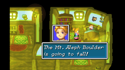
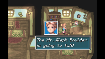
| Color Correction Example | |
|---|---|
| Before Color Correction | After Color Correction |
| Golden Sun on Game Boy Advance / GBI Without Color Correction | Golden Sun using csc/Game Boy Interface/Game Boy Advance.txt |
The Color Correction Setup menu controls the advanced color gamut correction and adjustment options on the RetroTINK-4K. The Apply Preset can be used to quickly load Color Correction profiles, such as the ones included on the 1.0 SD Card (more info on 1.0 CSC Profiles here).
Gamma and PQ
The input controls adjust how incoming RGB signals are converted from gamma space to linear light.
- Input Factor: Factor used to convert the input from gamma space to linear light. Input factor is the inverse gamma exponent. Can be adjusted between 0.10 and 5.00.
- Input Lift: Lift adds an offset (raises or lowers black level) to the input gamma conversion. Can be adjusted between -1.00 and 1.00.
- Input Gain: Gain multiplies the output of the input gamma conversion. Can be adjusted between 0.00 and 10.00.
- Output Factor: Available only in SDR, this is the factor used to re-encode the linear ligh output of the video pipeline back to gamma space. Can be adjusted between 0.10 and 5.00.
- SMPTE 2048 PQ: Available only in HDR, where the RT4K uses a perceptual quantizer instead of simple gamma, in order to tonemap the linear light signal into an HDR signal. The control sets the maximum brightness of the PQ in units of nits, which represents the maximum brightness of the tone mapping. Normally this is set to your TVs maximum nit level, however this function can be useful to dim the brightness of an HDR picture. Can be adjusted from 250 to 10,000.
Color Space Conversion
- Apply Preset: Opens the Load CSC Matrix menu, where users can load any saved CSC profiles from the SD card. Most use cases will involve simply applying a preset from the SD card, for example, to apply a color gamut correction to emulate a PVM. The RetroTINK-4K 1.0 SD Card release includes many presets.
You can explore the included CSC presets here.
Information on the Custom Color Matrix preset format can be found here.
- Custom Matrix: Allows the user to turn On or Off CSC by enabling/disabling the Input RGB to XYZ conversion matrix and settings applied to the Gamma/PQ.
- Prevent Clipping: Automatically scale the CSC matrix so that highlights are not lost at the cost of making the image dimmer. Can be set to On or Off.
- Saturation: Controls the color intensity. Lowering it turns the image black and white. Raising it makes the colors more intense. Can be set from -1.0 to +1.0.
Input RGB to XYZ
The user can manually adjust the matrix used to convert the input RGB data into XYZ colorspace. The RT4K automatically chains to correct conversion from XYZ to output RGB depending on the specified output colorimetry (e.g., BT709, BT2020, Adobe RGB, etc.). Each of the conversion functions can be adjusted between -1.75000 to +1.75000.
Advanced Controls
- Transfer Function: Can be set to "sRGB 0.055", "Rec.601/709 0.099", "SMPTE 240M 0.1115" or "Gamma". The various transfer functions linearize the low-end of the gamma curve to avoid bit loss. "Gamma" uses a simple gamma encoding.
- Bit Crush: Lowers the number of colors in the core video signal by reducing the number of bits per color. This is primarily intended for removing rounding errors that can occur in the original signal, e.g. when using GBI, as well as potentially removing noise in some limited cases. Alternatively, it can be used for aesthetic purposes to create a posterization or limited-color mode effect.
- Dithering: Can be set to "On" or "Off". Adds visually imperceptible random noise to the HDMI output to avoid banding and quantization artifacts due to the limit of 8-bit precision.
Black Frame Insertion (BFI)
| BFI is for adding motion clarity. This does not interpolate frames like various settings on modern displays. |
| Please use caution when using BFI. This setting may not be great for people who are sensitive to strobing lights. |
Black Frame Insertion (BFI) is a technique to improve motion clarity with high refresh rate monitors. As an example, a 60fps video source played on a 120hz monitor could have a black frame interstitially placed between every frame. The resulting "image-black-image-black" pattern can increase the perception of motion and fine details. If you have a higher refresh rate monitor, a customizable example can be viewed over at Blur Busters.
The use-case for Black Frame Insertion is to approximate the appearance of a CRT display, which would draw every line left-to-right, with the pixels dimming until they're replaced again for the next frame. Modern displays don't do this and never darken the pixels like this in the drawing process; this gives the effect of "blur" on moving parts of the picture. Black Frame Insertion is a crude but effective method of replicating the feel of looking at a CRT display, and gives the impression of better motion clarity.
BFI cannot be enabled unless the following two requirements are met:
- Set a supported Output Resolution and frame rate - Due to bandwidth constraints, BFI is limited to 1440p or lower resolution output. This also must be a high frame rate: either 100hz or 120hz.
- Set a supported Sync Lock Mode - BFI also cannot be enabled unless you are in Gen or Frame Sync Lock mode.
If both of these requirements are met, the BFI options will be unlocked.
- LCD Saver: LCD display panels may suffer from image retention when using BFI. The LCD Saver helps prevent this by inverting the order of (video frame)-(inserted frame) at the timer value set. LCD Saver can be set to 0, 1, 5, and 10 Minutes. When the frame order is inverted, it may create a momentary glitch in the video output. Note that setting the time value to 0 will display a message screen warning the user of possible LCD panel image retention.
- Min. BFI Limit: Can be set to "On" or "Off". Default "On". Disabling will disable safety limits for BFI strobe effects. Will prompt an additional warning screen when set to "Off".
BFI Control
| Black Frame Insertion (BFI) Settings | ||
|---|---|---|
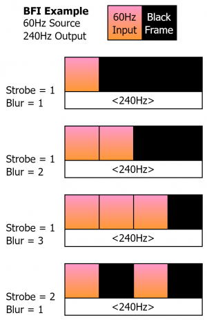
| Strobe: Strobe controls how the output frame rate is divided into the input frame rate. As depicted in the diagram, with Strobe 1, the 60Hz input frame is flashed one time at 240 Hz. At Strobe 2, the 60Hz input frame is flashed twice at 240Hz, with black frames in between. Alternatively, a 60Hz source within a 120Hz output would display for 1/2 of the time 120Hz output window.
Blur: Blur is a duty cycle modifier that works in relation to Strobe to change how many frames the source video is presented in relation to the black frames. In the example diagram (60Hz Source inside a 240Hz output), a Blur of 1 would display the source video 1/4 of the 240Hz window, a Blur of 2 would display the source video 2/4 of the 240Hz window, and a Blur of 3 would display the source video 3/4 of the 240Hz window. Some relationships of Blur and Stobe are locked, such as a 60Hz video source in a 120Hz output window, which would only allow a Blur of 1 (1/2 of the output 120Hz window). | ||
More information about BFI can be found at Blur Busters.
BFI Color
The BFI Color settings allows the user to change how the inserted frame appears.
The Blending Mode setting selects between the following functions:
- Solid: Creates a grayscale inserted frame that can be adjusted with any of the Red, Green or Blue BFI Color settings. A lower BFI Color numerical value is darker, higher is brighter.
- Alpha: In this mode, the inserted frame is a duplicated video frame with a transparent alpha overlay darkening the inserted frame based on the BFI Color setting. A lower BFI Color numerical value is darker/more opaque, a higher value is brighter/less opaque.
- Solid Color: Sets a solid inserted frame with an RGB-assignable color from the BFI Color selections.
- Alpha Color: Inserts a duplicated video frame with an alpha color overlay. The color of the alpha-blended frame is set from the R-G-B BFI Color values.
The Red, Green and Blue BFI Color values allow for customizable colors in the Solid Color and Alpha Color modes, and are an interlocked numerical valued for Solid and Alpha blending modes (R-G-B values cannot be adjusted separately).
Deinterlacer and Film
The Deinterlacer / Film Mode Setup menu allows you to adjust settings for use on interlaced sources, such as deinterlacing methods, apply LCD blending to progressive sources and setup Inverse Telecine.
While tweaking the options under the Mode and Motion Adaptive Settings sections, we suggest using the Pause Button to pause the video on a frame with motion. This will allow you to see the effects of the deinterlacing more easily.
Mode
There are six deinterlacing algorithms to choose from:
- Motion Adaptive - Uses an algorithm to determine whether to use Bob deinterlacing for areas of the screen that change, or Weave deinterlacing for areas that stay the same. Can be further tweaked in the Motion Adaptive Settings section.
- Weave - The current field remains on-screen while the next field is drawn, 'weaving' the two fields together. This is the same as 'disabled' in video players such as VLC, and will result in combing artifacts.
- Bob - Doubles the vertical height of each line to fill the full frame. This causes the image to appear as if it's moving up and down, since the two fields are not aligned in the interlaced signal, but preserves temporal resolution of interlaced video.
- Linear - Linear interpolated Bob (i.e., rather than a pure linedouble, line 2 is the average of lines 1 and 3, line 4 is the average of lines 3 and 5, etc.).
- Blend - The frame is created by averaging lines from the two most recent fields. Produces ghosting.
- CRT Simulation - Similar to Bob, but additionally changes scanline behavior to match that of interlaced content on a real CRT. If Scanlines have not been enabled, this mode will appear identical to Bob. See below for more details on this algorithm.
- LCD Blending - (Progressive sources) Averages the current frame and the previous frame. Produces ghosting that can blend flickering objects. (Interlaced sources) Averages the current field and previous same field, skipping the other field. Eliminates NTSC composite artifacts if the picture is completely still. Not recommended for gaming.
CRT Simulation
The CRT Simulation algorithm is unique enough to warrant its own section. It's used to to simulate the way 480i content is displayed on a real CRT: each frame of a 480i image is actually only 240 lines, and each new frame switches to using lines that were unused in the previous frame. Because of this, CRT Simulation will appear identical to Bob deinterlacing unless you use one of the Scanline functions enabled in the Processing / Effects menu (since they simulate the unused lines), and are viewing interlaced content.
CRT Simulation will also cause your crop settings to be displayed incorrectly, so be prepared to redo your crop after enabling this feature.
| The output frame rate of the RT4K must match the input signal's frame rate in order for the effect to be displayed correctly. This is important if you're using a PAL system, which run at 50 frames per second: if the RT4K is outputting at 60fps (as it usually does by default), the CRT Simulation will not appear correctly for PAL content! |
Motion Adaptive Settings
Motion Adaptive settings apply only to the Motion Adaptive Deinterlacing mode, allowing you to adjust how the Motion Adaptive Deinterlacing operates.
- Sensitivity: Adjusts the sensitivity of Motion Adaptive, between "Min", "Medium", "High" and "Max". The higher this is set, the more weaving will be present for moving parts of the screen, at the benefit of a stabler look for static parts of the screen. Many games will look just fine on the Min. setting, however several games may require Medium or higher. For example, Burnout 3: Takedown on PlayStation 2 has a subtle flickering and noise-like dithering that throws off the Motion Adaptive Deinterlacer for still parts of the screen.
- Noise Threshold: Adjusts how much low-level changes are ignored, so that the deinterlacer doesn't fall back to Bob deinterlacing unnecessarily. Useful for content that has noise and / or dithering present.
- Interpolator:Controls how the Bob function of the deinterlacer is calculated. The bob is either taken from the line above (Upper Field), line below (Lower Field) or the Average of the upper and lower lines.
- Detector: Can be set to "Zero-Lag", which favors the most current field. "Symmetric" favors the previous field, but allows for symmetric motion detection, which may provide cleaner results.
Bob Settings
The only Bob Setting here is the Bob Offset, which adjusts adjusts how far apart each field is from each other. It can be set between "-3" and "+3". This setting is useful for 240p games that were poorly ported to run at 480i, such as Mega Man Anniversary Collection on PlayStation 2.
Film Mode
The settings under Film Mode contain options to help process video content.
Inverse Telecine:
- 3:2 - In this mode, video content that was from a 24 Hz source converted to a 60 Hz signal will play back in a reconstructed 24 fps. This helps applicable video content play with its intended cinematic framerate.
- 2:2 - In this mode, the deinterlacer will rebuild progressive video output from 480i games that run at reliable/stable 30 fps, which effectively converts 480i into 480p. This will result in an increase in visual resolution and clarity. This is especially useful for PlayStation 2 where much of the library is 480i only.
Dejudder 24 Hz: This mode treats telecine material as a virtual 24 Hz source when using Gen Lock and Frame Lock Sync Lock, allowing for true 24 Hz output when combined with a 24 Hz output modeline. It can also be used with a 48, 72 or 120 Hz output modeline. This option only applies when a 3:2 source is successfully detected / deinterlaced.
Cadence Detection
The cadence detection menu offers controls to adjust the RetroTINK-4K's detection of content to pass to the the inverse telecine functions.
- Motion Digital, Motion CP, and Motion SDP: These values change the noise threshold for HDMI inputs, component/RGB inputs and composite/S-video inputs, respectively. Adjusting the noise threshold higher will decrease the detection of false positives, but may miss weaker or nosier telecine signals. Adjusting the threshold lower may increase false readings but allow less stable signals to be processed. Each value can be set from a range of 0 to 500.
- Threshold: Once a signal passes the check of the Motion thresholds, the Threshold number sets how many consecutive detections of a telecine pattern are required before the deinterlacer function activates. This may be helpful for noiser sources such as VHS to further filter out false detections.
HDMI® Receiver
The HDMI® Receiver Setup menu is where you control how the RT4K handles HDMI® In video. This menu is only functional when the HDMI® In port is the currently selected Input. If it is, this menu can be quickly accessed by pressing the ADC button at the top of the remote when HDMI® is selected as the input.
Input Decimation
| Input Decimation | ||
|---|---|---|
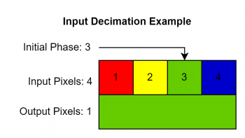
| Input decimation is a function to reduce the horizontal resolution of a given HDMI input. This works by taking the current input horizontal resolution, and reducing it as a division between the Input Pixels and Output Pixels settings. A display of the final output resolution after decimation has occurred is shown in parenthesis at the end of the Input Pixels field.
| ||
Colorspace
Colorspace has options to assign what colorspace the HDMI® input is using, as well as what method to use for 4:2:2 upsampling.
- 4:2:2 Upsampler: Determines how to process digital inputs that are using 4:2:2 chroma subsampling. Can be set to "Linear", which uses a bilinear filter for a smoother appearance, or "Nearest", which uses a nearest neighbor filter for a sharper look (but with more obvious aliasing).
- Input Range: Determines what color range to process the incoming digital signal as. "Auto" should be used unless there is a specific colorspace mismatch. Other settings include "RGB Lim.", "RGB Full", "YCbCr 601", "YCbCr 709", "xvYCC 601", "xvYCC 709", "YCbCr 601 (Full)" or "YCbCR 709 (Full)".
| This setting is independent of the HDMI range in the output menu. This should be consistent with the HDMI range of your console's output (e.g., the Wii U outputs Limited Range, so you set this to Limited Range, but you do not necessarily have to change the HDMI range in the output menu. |
MiSTer DV1
Information about MiSTer DV1 goes here.
- Auto-Decimate: Can be set to "Infoframe", "Measure", or "Off".
- Auto-Crop: Can be set to "On" or "Off".
A/DAC
- A/DAC Mode: Allows Analogue consoles that support the Analogue DAC to output an unscaled image to the RT4K. For more information, please visit the Analogue Consoles section of the System Specific Settings page.
- Off: The Analogue console sees the RT4K as a regular HDMI display.
- NTSC: The Analogue console sees the RT4K as an Analogue DAC with the region switch set to NTSC.
- PAL: The Analogue console sees the RT4K as an Analogue DAC with the region switch set to PAL.
| PLEASE NOTE: While using A/DAC mode, the connected Analogue console will output 240p with horizontal variable pixel repetition, in order to allow for cases such as SNES 512-column mode to be rendered correctly. This may cause some scaling settings to not behave how you expect. Nothing is broken, please adjust Input Decimation and Scaling/Cropping until you get the desired image, noting that the initial horizontal scale is 4x what you are probably expecting (2x if you're playing a game that uses 512-column mode), and THIS MAY CHANGE IN THE FUTURE. Additionally, A/DAC Mode when set to PAL will require manual aspect ratio adjustment, and when set to either NTSC or PAL will require significant cropping when used with the Mega Sg due to the Mega Sg's output having a significantly exaggerated overscan area. Due to limitations both with Analogue hardware and with our understanding of the Analogue DAC, none of these issues can be addressed automatically at this time. Finally, please also note that, like with the actual Analogue DAC, changing the A/DAC mode setting while your Analogue console is connected and turned on will result in improper operation from your Analogue console, and is not recommended. |
RGB and Component ADC
The RGB / Component ADC Setup menu is where you control how the RT4K handles analog inputs, such as the RCA, S-Video, HD-15 and SCART ports. This menu is only functional when an RGB or Component input is in use. If that is the case, this menu can be brought up by pressing the ADC button at the top of the remote when YPbPr, RGBS, RGsB, or RGBHV is selected as the input.
Sampling (ADC)
| Sampling (ADC) | ||
|---|---|---|
| ||
Sync (ADC)
- SoG Threshold: Sets the voltage level used to slice the video signal and generate a digital sync pulse. Adjusting this level may help with problematic sources. The voltage can be set between "0.00 mV" and "327.42 mV" in in 11.29 increments.
- Pre-coast: Sets the number of lines before vertical sync to switch from syncing with video source to internally generated sync. Can be set between 1 and 31 lines.
- Post-coast: Sets the number of lines after vertical sync to switch from syncing with video source to internally generated sync. Can be set between 1 and 31 lines.
The coast settings create a padding area away from the vertical sync pulse, so syncing to the horizontal doesn't encounter errors from off-spec signals or glitchy signal transitions. Adjusting Pre-coast and Post-cost values may be helpful when processing off-spec video sources.
- Wide Tolerance: Enables extra sync processing to help with 240p and 288p sources, such as arcade boards or NEOGEO, that may have sync issues due to malformed sync pulses. This should be turned off for normal use as it may cause artifacts for other systems.
Gain
- Pre-ADC: Changes the amount of analog gain applied to the signal before the ADC, functioning as a coarse contrast adjustment. Can be set between -0.7 and +0.8.
- Red,Green, and Blue allows fine adjustment of the individual color channel digital gain, functioning as a finer contrast adjustment per color channel. Can be adjusted between 1.000 and 1.996.
Offset
- Red,Green, and Blue offset provides per color black level / brightness adjustment. Values can be set between -100 and +100.
Auto Calibrate
Auto Phase
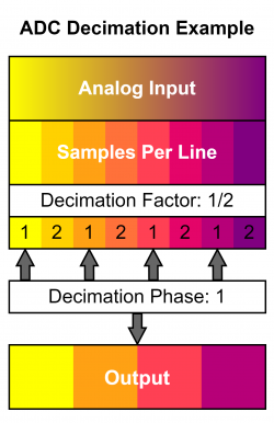
Any game screen is sufficient for automatic phasing, but it is recommended to use the 240p Test Suite or other sufficiently patterned screen for eyeballing results. whether you've set automatic sample detection using that menu, or you manually selected Decimation Factor in the ADC page, selecting Auto-Calibrate Phase makes the RetroTINK-4K automatically select the best Decimation Phase and Sub-Phase for your current picture and should give you the sharpest results. It is recommended you run this 3-5 times to make sure the same factors and phases are consistently chosen.
Auto Gain
The Auto Gain function will calibrate the gain levels for the current input, however it only works for RGB and YPbPr sources.
- To use Auto Gain, go to a game screen which has a patch of colour that should be pure white. When you enable the Auto Gain function, the RT4K automatically calibrates the Gain levels based on that white patch.
Auto Gain only works in calibrating the overall brightness Gain, not the individual color gain. You may need to manually adjust the individual colors a few ticks more for in the Gain section to get the true RGB code (255) for a given color. We highly recommend the use of the 240p Test Suite for this task.
Auto Gain must be calibrated on a per-console basis, meaning it will need to be set between different systems. This applies even across different units of the same system, such as two Super Nintendos, as their picture output will have degraded slightly differently.
Do NOT use this feature on Enhanced S-Video sources. The RT4K will try to calibrate Pb and Pr despite Enhanced S-Video's use of the SDP Decoder for color. Please calibrate gain on Green manually for Luma/Y only.
Sample Rate Detection
The Sample Rate Detection menu is where you control how the RT4K automatically detects the sample rate of a given analog source. This menu is only functional when an RGB or Component input is in use.
Sample Rate Detection Overview
The RetroTINK-4K can take advantage of sampling and scaling algorithms to seamlessly change settings when it detects a horizontal resolution change. This is useful for some analog retro gaming consoles, but requires knowledge of their "Master Sampling Rate." Please consult the table below to see which resolutions are available for consoles where automatic sampling detection is recommended.
If you do not see your console here, consider going to their System Specific Settings page and look for more information. Some consoles do not use this feature and will not be shown here.
| Console Name | ADC Sample Rate | Decimation Factor & Total (Active) Resolution | |||||
|---|---|---|---|---|---|---|---|
| 1/10 | 1/8 | 1/7 | 1/6 | 1/5 | 1/4 | ||
| Super NES | 3410 | 341.000 (256) | 682.000 (512) | ||||
| Sega Genesis/Mega Drive | 3420 | 342.000 (256) | 427.500 (320) | ||||
| Turbo Grafx 16/PCEngine | 2730 | 341.250 (256) | 682.500 (512) | ||||
| Sony PlayStation | 3413 | 341.300 (256) | 426.625 (320) | 487.571 (384) | 682.600 (512) | 853.250 (640) | |
| Sony PlayStation 2 | 3432 | 343.200 (256) | 429.00 (320) | 490.286 (384) | 686.400 (512) | 858.000 (640) | |
| Console Name | ADC Sample Rate | Decimation Factor & Total (Active) Resolution | |||||
|---|---|---|---|---|---|---|---|
| 1/10 | 1/8 | 1/7 | 1/6 | 1/5 | 1/4 | ||
| Sony PlayStation | 3406 | 340.600 (256) | 425.750 (320) | 486.571 (384) | 681.200 (512) | 851.500 (640) | |
| Sony PlayStation 2 | 3456 | 345.6 (256) | 432 (320) | 493.714 (384) | 691.2 (512) | 864 (640) | |
Once you know the master sampling rate of your console, set that console's ADC Sample rate in the "Sample Rate Detection" menu under ADC Sample Rate, and turn both "Auto Dec. Factor" and "Auto Dec. Phase" to "On." Once you enable those options, if you know which resolutions you'll use, scroll down to that resolution to enable that horizontal resolution's detection and the RetroTINK-4K should automatically switch to a different set of settings whenever it detects that particular resolution is used. This process will help automatically set Decimation Factor and Decimation Phase in the ADC setup.
| You may be tempted to turn on every resolution, but if you know your console won't use it, consider turning that resolution off to help with the detection speed. |
Control
- Auto Dec. Factor: Turns on Sample Rate Detection
- Auto Dec. Phase: Turning this on makes the RT4K select phase for you. This disables the Decimation Phase setting in the ADC menu.
- Detection Mode: Can be set to "Generic Console" or "Saturn". Generic Console covers most systems since they have a fixed video clock. A special Saturn mode is needed due to the Saturn's variable master video clock.
- ADC Sample Rate: Tells the RT4K how many samples to take in each line.
Progressive Detection & Interlace Detection
Each line shows the result of the ADC Sample Rate divided by a different Decimation Factor: 10, 8, 7, 6, 5, and 4, respectively.
SDP Decoder
The SDP Decoder Setup menu is where you control how the RT4K handles Composite and S-Video. This menu can be quickly accessed by pressing the ADC button at the top of the remote when S-Video or Composite are selected as inputs.
Gain and Balance
- Brightness: Adjusts the brightness of the image. Can be set between "-100" and "+100".
- Contrast: Adjusts the contrast of the image. Can be set between "-100" and "+100".
- Chroma: Adjust the saturation of the image. Can be set between "-100" and "+100".
- Phase: Adjusts the tint of the image.
- Blue Only: Displays a greyscale depiction of the blue colour values, with white being full blue and black being no blue.
- Setup: Can be set between 0 IRE and 7.5 IRE.
Processing
These controls will adjust how the RT4K handles the processing of the Composite video signal.
2D Processing
- 2D Y/C Filter: For composite video to be displayed, the "chroma" (color) and "luma" (black and white) parts of the signal must be separated. The RetroTINK-4K offers a variety of filter functions to perform this signal separation. The 2D functions available are "2D Adaptive", "2D Fixed" and "Notch".
- 2D Bandwidth: 2D bandwidth determines how much detail to try to preserve when separating luma and chroma components. Higher bandwidth maintains more detail but also introduces more artifacts. Can be toggled between "Low" and "High" settings.
- Chroma Bandwidth: Controls a low pass filter on the chroma signal, may help to remove rainbowing and other artifacts.
- Sharpness: Artificially sharpens the image. Can be set between "0" and "15".
- CTIE: Can be set between "0" to "3". CTIE sharpens the chroma channels using the luma channel as a guide.
3D Processing
- 3D Comb Enable: When set to "On", this will enable the RetroTINK-4K's 3D Comb Y/C Filter. The 3D Comb filter will analyze three consecutive fields of the same location in the video. If there is no detected motion across these 3 samples, the filter can operate with very high accuracy, effectively replicating the quality of S-Video. When changes across the sampled fields are detected, the algorithm will fall back to 2D Comb filtering, a technique that does not rely on previous frames of video to inform the filter. This "3D when the screen is still, 2D when in motion" is similar to the methods employed when using Motion Adaptive Deinterlacing. 3D Comb can be adjusted further with the Noise Threshold setting.
- Noise Threshold: Adjusts the 3D Comb sensitivity to bias 2D or 3D filtering. "Low" will quickly fall back to 2D filtering when motion is detected, while the Medium and High settings will bias the 3D filtering. "Default" is calibrated between "Low" and "Medium".
Sync (SDP)
Adjusts how the RetroTINK-4K syncs and locks onto the Composite signal.
- H-Lock Speed: Can be set to "Auto", "Slow", "Medium" and "Fast".
- Standard: Changes the analog signal standard for composite video decoding. Can be set to "Auto", "NTSC", "PAL", "SECAM", "NTSC-443", "PAL-M", "PAL-N" and "PAL-60".
Enhanced S-Video
| S-Video | Enhanced S-Video w/ Optimizations |
|---|---|
The RetroTINK-4K offers a special mode for processing S-Video (Y/C) video signals known as Enhanced S-Video. By bringing S-Video into the 4K's HD15 port, the signal can be fed through the SD and High-Resolution analog-to-digital converters simultaneously. This method offers higher resolution luma digitization, while enabling Decimation and Auto Phase on S-Video sources. To enable Enhanced S-Video, Y/C must be connected to the HD-15's Green/Red pins respectively, and the RetroTINK-4K's input must be set to Y/C on G/R (Enc.).
See Enhanced S-Video Wiring for more detailed information on how to bring S-Video into the HD-15 input.
- Chroma Shift: Adjusts the horizontal alignment of the chroma signal when using Enhanced S-Video mode. Can be set from "-100" to "100" Default is "0".
Audio Input
The Audio Input Setup menu is where you'll find options regarding the RT4K's handling of audio, such as the sampling rate and overriding which audio input is in use. More information can be found in the Alternate Audio Inputs and Inputs section.
Sampling (Audio)
- Sample Rate: Set the RetroTINK-4K's audio output sample rate. You can choose either 48khz and 96khz.
- Pre-amp Gain: Boost or attenuate the audio output gain. Can be set from -24dB to +28dB.
Source
- Input Override: Here you can override the current audio source with an alternate input, choosing between RCA, HD-15, SCART, Front S/PDIF or Off.
- Input Swap: Allows you to enable mono to stereo function (1 signal to two speakers) with Mono (left) and Mono (right) selections, or swap the left and right audio channels with the L/R Swap selection.
Surround Sound Input and Support
If your console is using Dolby Surround, it is likely using compressed surround sound encoded in Stereo Audio. There is no setting to adjust for this as it is entirely up to your receiver to decode Dolby Surround. The RetroTINK-4K simply passes this information through.
If your console outputs via Optical Audio, it will send compressed surround sound, which is properly decoded to the output.
If your console outputs LPCM via HDMI®, the RetroTINK-4K will simply pass through up to 8 channels of surround sound to its HDMI® output.
System
The System selection of menus relate to the RetroTINK-4K itself, including the On-screen display, firmware updates, and displaying various status screens.
OSD and Firmware
Banner Image
This menu allows you to load in your own banner. The default banner is the RetroTINK-4K banner, but community banners are also included, like FirebrandX's banner displaying Firebrand from Demon's Crest, and moon banners (which intentionally do not display the moon in a perfect circle).
Here's some information on how banners work on the RT4K:
- Banners are stored in the "image" folder of the SD card.
- Banners must be 24-bit BMPs in order to work with the RT4K.
- 320 x 128 is the recommended pixel dimensions. It can be larger, however only the upper-left 320x128 pixels of the image will be drawn.
- An RGB value of "255, 0, 255" (magenta colour) will be treated as transparency.
- Banners are saved as part of the profile.
- If a profile doesn't have a banner image specified, the file named "default.bmp" will be loaded instead. This lets you determine your own default banner image.
On Screen Display
This section allows you to adjust facets of the On Screen Display, including the menu.
- Position - This lets you set whether the menu is displayed on the Left side of the screen, the Center, or the Right side of the screen. This is set to "Left" by default.
- Auto-Off - Lets you determine how long the menu will wait before disappearing (as if you pressed the menu button). This is set of "Off" by default, but you can set it to turn the Menu off after up between 10 - 100 seconds (and anything in-between in 10 second increments).
- Hide Input Res. - Turning this on will mean the RT4K will not display the current input and resolution in the top-right corner of the screen every time it changes. This is useful if you're capturing or streaming games that switch resolutions.
- Enable Debug OSD - This option allows you to permenantly display one of the three Status Pages or the Diagnostic Console.
Firmware Update
This option allows you to Check the SD card for the two files needed for installing new firmware to the RetroTINK-4K. For more information on how to install new firmware, head to the Firmware Updates section.
Status
Displays the Status menu, letting you learn more about the current status of the RetroTINK-4K. For more information, visit the Device section of our GUI Map.
Diagnostic Console
Shows the 30 most recent actions in the RetroTINK-4K's operations. Or something?
About
Displays the About Page, containing the following information:
- About
- Device - Displays information about the RT4K's hardware version.
- FW Version - Displays the current firmware name.
- Device ID - Displays the ID of the RT4K.
- Resources
- Website - www.retrotink.com
- Discord - discord.gg/jE6deAhjCM
- Wiki - consolemods.org/rt4k
- Special Thanks To:
- RetroRGB - GameSack - FirebrandX - Wobbling Pixels - Extrems - CouryC - John Linneman - Try4ce - Artemio - Blur Busters - Voultar - Old Kid - MinotaurZombie - teen Nick - Chungo - Mr. Moro - Guspaz - SquidHominid - Mizox - blizzz - Supercowabunga - Jeff Chen - pram0d - atrac17 - Cyo - 8bitesquire - Fenris Wolf Retro - Ace - Kuro Houou - ScarletSprites - wizzo - CGQ - TechnicalMonkey - EposVox - Derf - IceStrike256 - RegentOfOrigin - Kjeld - cobhc - KBABZ
- Names are ordered to favour formatting, and are otherwise in no particular order.
- Names are ordered to favour formatting, and are otherwise in no particular order.
- RetroRGB - GameSack - FirebrandX - Wobbling Pixels - Extrems - CouryC - John Linneman - Try4ce - Artemio - Blur Busters - Voultar - Old Kid - MinotaurZombie - teen Nick - Chungo - Mr. Moro - Guspaz - SquidHominid - Mizox - blizzz - Supercowabunga - Jeff Chen - pram0d - atrac17 - Cyo - 8bitesquire - Fenris Wolf Retro - Ace - Kuro Houou - ScarletSprites - wizzo - CGQ - TechnicalMonkey - EposVox - Derf - IceStrike256 - RegentOfOrigin - Kjeld - cobhc - KBABZ
SD Card and Profiles
The RetroTINK-4K includes an SD card with a set of Profiles, CRT Masks, Color Correction Profiles and more from the talents of FirebrandX, Wobbling Pixels, Exrems, Kuro Houou, pram0d, Cyo, MrMoro, austinbroth, Chungo, and (anyone else I'm forgetting). This area includes a mirror to download the stock RetroTINK-4K 1.0 Full SD Card, as well as a comprehensive list of every profile included with the release.
| Name | Description |
|---|---|
| SD Card Version 1.0 | A downloadable.zip copy of the 1.0 launch SD Card, including the stock firmware and included Profiles. |
| Profiles Version 1.0 | A comprehensive breakout page detailing every Profile included with the 1.0 launch SD Card. |
New SD cards, firmware, and profiles are now available in the Firmware Repository.
System Specific Settings
System Specific Settings is all about highlighting how you can use the RetroTINK-4K's various features to improve the experience of using your video game systems beyond just plugging them in. This can range from setting 1:1 pixel aspect ratio for Super Game Boy on the SNES, to dovetailing with the Sharpscale Plugin on the PlayStation TV.
- Due to its sheer size, this section has been broken out into its own subpage, which can be found here.
Additional Guides
Custom CRT Masks
The RT4K allows for the use of custom CRT Mask overlays via the Masks menu. This is primarily intended to give an effect similar to CRT shadow, slot and aperture masks that stretch across the screen (as opposed to scanlines, which affect the picture underneath). The RT4K uses mask images and tiles them across the screen to replicate the effect.
- To easily make your own CRT Mask, we recommend using infinest's Mask Editor tool.
Here's what you need to know when it comes to making your own CRT Mask:
- Custom CRT Masks must be saved as 32-bit .BMP files.
- The maximum dimensions of a CRT Mask image is 16 x 16 pixels. They can be smaller, which will result in denser tiling of the mask across the screen.
- A color value of 128 will be neutral, while 0 will completely black out the corresponding pixel. 255 will double the input value (although this will be clamped).
- Custom CRT Mask images should be stored in the "mask" folder on the SD card.
| CRT masks will NOT adhere to the pixel grid like the RT4K's scanlines will. If you want them to adhere to the pixel grid, you'll need to have your shadow mask image match the dimensions of a single upscaled pixel, but this will vary depending on many factors, and so should be paired with a specific Profile you have in mind. Since Mask images have a maximum size of 16x16 pixels, this inherently means that the upscaled pixels of the input image cannot exceed 16x16 pixels in RT4K's output resolution. |
Custom Color Matrix
RetroTINK-4K Custom Color Matrix Instructions - Custom color gamut correction factors can be loaded by the user. Each file is a set of csv values describing gamma and Input RGB -> XYZ transforms. The RT4K will automatically apply the correct XYZ -> Output RGB matrix depending on the specified HDMI output colorimetry.
The csv file has 14 entries (all floating point) on a single line:
- 1: Input Gamma
- 2: Input Lift
- 3: Input Gain
- 4: Output Gamma
- 5: Transfer Function (0 = sRGB, 1 = Rec. 601/709, 2 = SMPTE 240, 3 = Conventional Gamma)
- 6-14: Input RGB -> XYZ Matrix Coefficients
Thanks to Dan Mons, Keith Raney (https://github.com/danmons/colour_matrix_adaptations/tree/main) and Extrems (https://www.gc-forever.com/wiki/index.php?title=Game_Boy_Interface) for providing technical assistance and example data.
Custom Modelines
The RetroTINK-4k supports user generated modelines for custom output resolutions, these are accessible by the RES1-RES4 buttons directly on the remote control.
These can be edited on the SD card in the modelines folder, these are named custom1.txt, custom2.txt, custom3.txt, and custom4.txt (corresponding to the remote buttons)
Modelines are stored as a single line of 12 comma seperated values. For example:
1690, 130, 184, 624, 1, 1420, 3, 10, 60, 1, 69.420, "1420p60"
- 1. Horizontal Active Pixels
- 2. Horizontal Front Porch Pixels
- 3. Horizontal Sync Pixels
- 4. Horizontal Total Blank Pixels (Active + Front Porch + Sync + Back Porch)
- 5. Horizontal Sync Polarity (1 = positive, 0 = negative)
- 6. Vertical Active Lines
- 7. Vertical Front Porch Lines
- 8. Vertical Sync Lines
- 9. Vertical Total Blank Lines (Active + Front Porch + Sync + Back Porch)
- 10. Vertical Sync Polarity (1 = positive, 0 = negative)
- 11. Nominal Frame Rate (floating point value) when in Triple Buffer mode
- 12. String Text Name (not used currently)
To easily make your own custom modelines, we recommend using Guspaz's RetroTINK 4K Video Timings Calculator.
For example, users of 1536p displays like the iPad lcd monitors can use the following modeline:
2048, 48, 32, 160, 1, 1536, 3, 4, 44, 0, 60.0, "1536p"
Custom Modelines Tutorial
| This is not an exact science. There are many variations of modelines and display technologies, and your particular display may not agree with the modeline you are trying to feed it, despite timings falling under 600MHz and your display's feature claims. Unfortunately every combination of display and modeline cannot be tested by Mike alone and we depend on the community to help give information regarding modelines and particular displays. |
Follow these steps to correctly use the Custom Modelines Feature. For this example a 1080p180 modeline will be used for a monitor that cannot reach 240fps, but a 2-1 BFI cadence is still possible.
- Find the resolution and framerate of your display. For this example: 1920x1080p is the resolution and 180fps is the framerate.
- Visit the RT4K Video Timings Calculator
- Enter your desired Horizontal Pixels, Vertical Pixels, and Refresh Rate (Hz). In this example, 1920 goes into horizontal pixels, 1080 goes into vertical pixels, and 180 goes into the refresh rate.
- Click into another field to update the Timings chart.
- Note that the Timings chart will show some values in green and some values in red. Green Values indicate the timing is within the 600MHz output clock of the RT4K. Red means the timing exceeds the 600MHz output and the RT4K will not work with it.
- Make your way down to "RT4K Custom modelines" and note the text for the modelines that are green. In this example you want the following bits of text
- 1920, 176, 208, 768, 0, 1080, 3, 5, 122, 1, 179.98, "1920x1080p179.98"
- 1920, 48, 32, 160, 1, 1080, 3, 5, 98, 0, 179.98, "1920x1080p179.98"
- 1920, 8, 32, 80, 1, 1080, 84, 8, 98, 0, 180, "1920x1080p180"
- 1920, 8, 32, 80, 1, 1080, 84, 8, 6, 0, 180, "1920x1080p180"
- Take your SD Card out of your RT4K and connect it to your computer. Enter the "modelines" folder in the root of your SD Card. You should note there are 5 files: "_Mode Line Instructions.html" has the information noted in the above section. "Cutom[number].txt stores modeline data.
- Open each modeline file and put one modeline noted above into each file. If you have more than 4 you will have to come back to this step, as the RT4K can only use 4 at a time.
- Save each file. Place your SD Card back into your RT4K.
- With your RT4K on, press the Res1, Res2, Res3, and Res4 on the remote until you find a modeline that is stable.
- You may have to repeat this tutorial and tweak your values until you find something your display agrees with. As an example, a 180Hz modeline may not work with a Super NES, which would need a Refresh Rate of 180.03Hz for its unique refresh rate.
Custom Input Modes
Custom input mode definitions improve the handling of input sources that are detected as "Unknown" by the RetroTINK-4K. Unknown input sources are often displayed as a small strip in the middle of the screen, with parts of the image missing. With the correct definition the image will be automatically cropped and scaled to the desired aspect ratio. Up to 24 definitions can be added to the "input_database.txt" text file in the "inputmodes" folder on the SD card.
The parameters for each custom input mode is a single line of csv values with the format:
1. Minimum acceptable frame rate (floating point)
2. Maximum acceptable frame rate (floating point)
3. Minimum acceptable number of lines per frame (integer, note interlaced signals are treated on a frame, not field basis, so 525 for 480i or 625 for 576i)
4. Maximum acceptable number of lines per frame (integer)
5. Horizontal Sync Polarity (integer, 0 = don't care, 1 = negative, 2 = positive)
6. Vertical Sync Polarity (integer, 0 = don't care, 1 = negative, 2 = positive)
7. Interlaced (integer, 0 = expect progressive, 1 = expect interlaced)
8. Horizontal Sync + Back Porch Pixels (integer)
9. Horizontal Active Pixels (integer)
10. Horizontal Total (Front Porch + Sync + Back Porch + Active) Pixels (integer)
11. Vertical Sync + Back Porch Lines (integer)
12. Vertical Active Lines (integer)
13. Vertical Total (Front Porch + Sync + Back Porch + Active) Lines (integer)
14. Actual Horizontal Sampling Pixels (integer)
15. PAR Factor (float)
16. Desired Slot Number in Profile (integer 1-24)
17. String Name for Mode
If an RGB or YPbPr signal does not match an existing known definition, the RT4K will attempt to find a match from the database file using parameters 1-7. If a match is found, parameters 8-15 are then used for sampling and cropping the signal. The save slot inside the profile file that is used for this custom input mode is set by parameter 16. The final parameter is the name for the custom input mode, which is shown in the RT4K menu and input detection popup.
Examples:
This is the input mode definition for a standard 480i signal: "55.0, 65.0, 523, 527, 0, 0, 1, 122, 720, 858, 18, 240, 263, 1716, 0.90909, 10, 480iCustom"
Input mode defintion for Sega NAOMI provided by Aru: "59.0, 61.0, 529, 531, 1, 1, 0, 122, 749, 858, 34, 480, 495, 2200, 0.90909, 11, Sega Naomi"
Notes:
- Parameters 8-13 can be determined either from technical documentation of the source system, or by trial and error.
- The actual sample rate (parameter 14) can be different from the "canonical" sample rate (item 10) for the input mode.
- BT.656 480i signals are conventionally sampled with 858 pixels/per line with a PAR of 10/11 (0.9090). However, the modeline specifies that the RT4K should actually sample at 1716 pixels per line (which will result in improved image quality due to oversampling). The RT4K will use the "canonical" sample rate, the PAR factor and the actual sample rate such that the final image is scaled correctly.
Preparing your TV for use with the RT4K
Try these options to prepare your TV for use with the RT4K. You may need to do a google search for [your tv model number] and the setting you are looking for, as every manufacturer uses a different name for the feature.
- Turn off Motion Interpolation. This is a very big contributor to latency. Disabling this also helps make sure post processing effects render correctly
- Turn off every setting if it has an off switch. Smart TV settings typically add to latency.
- Turn on Game Mode. This helps turn most off most options, but you may need to manually turn off other settings. Game mode should instruct the display to let the RT4K drive the display rather than letting the display dictate how to handle colors and effects. Turning game mode on is usually the best way to lower latency.
- Turn on PC Mode. This typically forces the PC to display all colors and disables chroma subsampling on a TV. PC mode on and off is the difference between post processing effects looking correct and not rendering correctly. See below for an example.
- Locate your TV's Black Frame Insertion feature. If your TV has BFI you may want to implement that while the RT4K renders in 4K to reap the benefits of 4K post processing and keeping your resolution high.
- Enable HDR and make sure all previous steps are repeated. Some displays will turn previously unselected options back on when you enable HDR.
Community Resources
This section provides a list of helpful resources and additions to the RetroTINK-4K. Click the link in the name to go directly to an item's page.
Accessories
| Name | Author(s) | Description |
|---|---|---|
| SCART2VGA Adapter | jeffqchen | A 3D-printed adapter for the RT4K's SCART port, turning it into a second rear HD-15 port. |
| SCART-Lock | Kytor Industries | A sleeve that fits over most angled SCART connector heads. Has two screws that go into the screwholes flanking the RT4K's SCART port for a secure fit, much like the HD-15 port. |
| Vertical Stand | Retro Frog | A vertical stand for the RT4K, with a holder for the remote control. Available as a .stl file for 3D printing. |
| Remote Mount | Laser Bear Industries | A mount for the RT4K's remote so it can be mounted on a wall or other flat surface. Also works with the RT5X's remote! |
| Wall Mount Kit | Laser Bear Industries | A wall mount for the RT4K, including VESA mounting holes and cable strain relief brackets. |
| Fan Mount Kit | Laser Bear Industries | A fan kit that replaces the white cover on the left side of the unit (fan sold separately). While the RT4K does not need a fan for normal operation, one may be handy if the device does not have good airflow. |
| DB15 to S-Video and CVBS Adapter | Laser Bear Industries | An adaptor that allows S-Video and CVBS (Composite) signals to be fed into the DB15 port. Do note that the DB15 port does not accept audio, which must instead be fed into the 3.5mm jack. |
Downloads and Web Pages
Various downloads and websites for use with the RT4K, including 3D printed files and custom modelines.
| Name | Author(s) | Description |
|---|---|---|
| Fat32format (GUI) | Ridgecrop Consultants | A utility to format SD and microSD cards larger than 32GB with FAT32, as needed for the RetroTINK 4K. |
| RetroTINK Firmware Repository | Squid Hominid | A collection of all release and experimental firmware for RetroTINK devices, as well as SD card images with updated firmware and profiles. |
| RT4K Schematics | Mike Chi | A .zip file containing the RT4K schematics with dimension measurements, and a .step CAD model. These are ideal for designing your own shell or other parts that need to physically interact with the device in some way. |
| Video Timings Calculator | Guspaz | Generates custom Output modelines. |
| Mask Editor | infinest | Lets you manually create, load, and export your own CRT Mask images for use on the RT4K. |
Community Profiles
Helpful Profiles created by the RetroTINK-4K community. These are not contained on the SD Card by default: to add them, connect the RT4K's SD card to your computer, then drag the profile's .rt4 file into the "profile" folder on the SD card.
| Name | Author(s) | Description |
|---|---|---|
| RetroTINK 4K NTSC & PAL Profiles | Wobbling Pixels | A link to the latest updated version of the Wobbling Pixels RetroTINK 4K profiles. IMPORTANT: Read the "How to install and update profiles" txt file. |
| Prof_gLX RT4K Profiles | Prof_gLX | Current profiles include 3DO via RGB in 240p and 480i modes, Atari 2600 Composite, GBA Consolizer, Neo Geo MVS, Hi-Def NES (HDMI Mod). Up to date as of 2023-12-17. See "Readme - Prof_gLX Profiles.txt" for details. |
| RegentOfOrigin Profile Packs | RegentOfOrigin | N64 NTSC HD Retrovision profiles and a collection of 7th and 8th Gen simple HDMI profiles. Up to date as of 2023-12-26. |
| VHS Capture Profile | Bob from RetroRGB | The default RT4K profile tweaked for the purposes of VHS tape video capture.using the front Composite / S-Video ports. |
| All community profiles can now be found on the firmware repository. These are rounded up and released with every stable firmware release. https://retrotink-llc.github.io/firmware/4k-sdcards.html |
Community Masks
Comunity masks can be found in the SD Card Images on the Firmware Repository under Masks.
Community Banners
Banners made by the RetroTINK-4K community. These should be placed into the "banners" folder on the SD card. Refer to the OSD and Firmware section for more information on how to select a banner for your profile.
| Preview | Name | Author(s) | Description |
|---|---|---|---|
| MiSTerFPGA | Pezz82 | The MiSTer FPGA logo, as a banner! | |
| RT4K-RGB | ArielAces | Rainbow RGB banner of the RetroTINK-4K logos. | |
| Retrowave | ArielAces | A Retrowave-style RetroTINK-4K banner. | |
| NES-SMB3 | ArielAces | A banner styled after the NES and Super Mario Bros. 3. | |
| SNES-SFII | ArielAces | An SNES Street Fighter II banner. | |
| Chrono Trigger | ArielAces | A Chrono Trigger-themed banner. | |
| Sega Sonic A | ArielAces | A Sonic the Hedgehog-themed banner. | |
| Sega Sonic B | ArielAces | A banner themed after the Sonic the Hedgehog logo. Ooo! | |
| #EmulationIsForQuitters | ArielAces | A banner made for 8BitEsquire after his Emulation is for Quitters hashtag. | |
| $10 FPGA inside | ArielAces | A banner made for 8BitEsquire after the $10 FPGA in-joke in the RetroTINK community. | |
| RetroRGB | ArielAces | A banner made for Bob from RetroRGB after said website. | |
| The Lag is Real! | ArielAces | A The Lag is Real! banner made for Bob from RetroRGB. Features the faces of Bob and Art of fgcOS. |
Video Guides
Various videos that help with using the RetroTINK-4K.
| Video | Author | Description |
|---|---|---|
| My Life in Gaming | Guide on the possibilities of the HDMI input, including scanlines on retro and retro-style games presented in HD. Also has an overview on the analog inputs. | |
| FirebrandX | Guide on how to make an optimal sampling RetroTINK 4K profile. | |
| Wobbling Pixels | Guide on how to use Wobbling Pixels' profiles included on the SD card. |
Other Resources
For other cool things that don't really fit anywhere else.
| Item | Author(s) | Description |
|---|---|---|
| Mike Chi | The image used for the sticker on the SD Card that comes with every RT4K. |
FAQ / Troubleshooting
Support Questions
Basic Troubleshooting Steps
Confirm the following
- Your power supply is capable of 5V and at least 2A (or 5V and at least 10W)
- SD Card is formatted with FAT32
- Input is 1080p60 or less
- Correct input is selected on the RetroTINK-4K to match your device. Confirm by cycling through the variations on the Input menu at the top of the RetroTINK-4K menu
- Output cable is rated for HDMI 2.0 (18Gbps). Narrow down to this or display support issue by using 480p button on bottom half of remote
- Your display supports 4K. Narrow down to this or HDMI issue by using 480p button on bottom half of remote
- Motion Interpolation is off. Called different things by different manufacturers (Motion Smoothing, Tru(e) Motion, etc.), this creates extra frames that aren't present in the source and can cause flickering or ghosting, especially when using scanlines. Check your TV's manual for how to disable this feature
- Chroma Subsampling is set to 4:4:4 (often incorrectly called "RGB"), instead of 4:2:2. When incorrectly set colors may distort and fine details may be lost. This can be set on many displays by setting the input to "PC Mode". Check your TV's manual for how to enable this feature
Try this
- Connect your console directly to the RetroTINK-4K and the RetroTINK-4K directly to your Display without splitters (unless absolutely necessary), AVRs, etc.
- Download the newest stable firmware and put BOTH files on the root of the SD card (overwriting any
rt4kup.binfile that already exists). Hold the reset button on the back of the device as you plug in the device or press the power button on the remote. Wait for it to update. - Reload the profile you were using to reset any changes. Download it again if needed. Reload the default if you're too far gone.
| ExpandProblems with the SD Card |
| ExpandMy 4K blinks yellow and then turns off! |
| ExpandThis doesn't look right with my display!/There's jailbars with post processing!/This doesn't look as good as I thought it would! |
| ExpandThe output is too sharp! It’s too blocky! |
| ExpandThe picture is too bright with HDR on! |
| ExpandThe picture is too dark with scanlines! |
| ExpandI get picture from my RT4K but not my console?!? |
| ExpandI've tried so many things and would really appreciate help! |
Store / Pricing Questions
| ExpandWhen will the next batch become available for purchase? |
| ExpandI want to buy two RT4K’s / How many can I buy? |
| ExpandHow much is the RetroTINK-4K? |
| ExpandWhat are the dimensions and weight for the package? |
| ExpandIs there a payment plan available? |
| ExpandCan I buy a used RT4K? |
| ExpandI live in the UK and want a RT4K! |
| ExpandI don't live in the USA! How can I buy a RT4K?? |
Compatibility Questions
| ExpandDoes the RT4K support Elgato? I heard RetroTINK doesn’t support Elgato. |
| ExpandIt doesn’t work with my 1080p capture card! |
| ExpandIs there HDCP Support? My display says "HDCP Active" on the top right of the screen. |
| ExpandCan I use GCVideo Lite cables with my RT4K? |
| ExpandIs the RT4K worth it for consoles from the 8th generation (PS4 / Xbox One) and beyond? |
| ExpandCan I use the RT4K to scale my set top box? |
| ExpandCan I upscale VHS/DVD? |
| ExpandIs the RT4K compatible with MiSTer and/or MiSTER Direct Video? |
Hardware Questions
| ExpandIs there only 4K output? |
| Expand
Does the RT4K pass through 4k input? Is the input HDMI® 2.1? |
| ExpandWhat is the recommended power for the RT4K? |
| ExpandCan I use my TV’s USB port for power? |
| ExpandDoes the RT4K use USB-C or Micro USB? |
| ExpandCan any input also be used for output? |
| ExpandIs the RT4K rack mountable? That's the RU length? |
| ExpandIs there an S-Video or Composite port? If so, where are they? |
| ExpandThe SCART port is loose! Can I get a return? |
| ExpandWhat kind of memory card should I use? |
| ExpandWhat are the external device communication abilities of the RT4K? Can I use it with WiFi? Bluetooth? Is there serial support? |
| ExpandIs there surround sound support? |
| ExpandWhat’s the VGA Pin Layout? |
| ExpandWhat’s the SCART Pin Layout? |
| ExpandIs there ARC / eARC support? |
Software Questions
| ExpandDoes resetting or updating the unit delete my profiles? |
| ExpandCan you run emulators on the FPGA? |
| ExpandDoes the RT4K automatically switch resolution? |
| Expand
Does the RT4K automatically switch to a detected source? |
| ExpandWhy isn't there automatic source switching? |
| ExpandDoes the RT4K support [240p, 480i, 540p,786p, 1080i, 1536p] output? Does it support my HDCRT? |
| ExpandCan the RT4K record to the SDCard? |
Comparison Questions
| ExpandMy display does nearest neighbor upscaling, why would I need this? |
| ExpandHow does this compare to a CRT? |
| ExpandHow does this compare to the mClassic? |
| ExpandHow does this compare to the 4K Gamer Pro? |
| ExpandIs this better than emulation? |
| ExpandThis doesn’t make my game look any better than on my TV |
| ExpandWill this scale HDMI faster than my TV? |
Recommendation Questions
| ExpandWhat's the best Capture Card to use with the RT4K? |
| ExpandWhat's the best Best HDMI® Splitter to use with the RT4K? |
| ExpandWhat's the best best HDMI® Switch to use with the RT4K? |
| ExpandWhat's the best HDMI® Cable to use with the RT4K? |
Miscellaneous Questions
| ExpandI want to use a scaler into the HDMI® input port of the RT4K |
| ExpandI want to use the mClassic on the RT4K input! |
| ExpandI want to mClassic the output! |
| ExpandI want to use 4K Gamer Pro on the RT4K output. |
| ExpandI lost the remote! |
| ExpandCan I enable HDR on my input? |
| ExpandI lost my USB Cable! |
| ExpandSomething is wrong with my unit! |
| ExpandI've checked the Discord channel and they were unable to help me / There is definitely something wrong with my unit after extensive testing! |
| ExpandDoes this work with the RT5X remote? |
RetroTINK-4K GUI Map
The GUI Map lists every single menu and menu item on the RetroTINK-4K, along with a brief description of what it does. For more information on them, click on a header to be taken to the appropriate section on this page.
GUI - Basic Setup
GUI - Input Selection
More information concerning inputs can be found in the Inputs section.
| HDMI® | |
|---|---|
| HDMI® | Selects the HDMI® In input. |
| Front | |
|---|---|
| Composite | Selects the front composite input. |
| S-Video | Selects the front s-video input. |
| Rear RCA | |
|---|---|
| YPbPr | Selects the rear RCA YPbPr input. |
| RGsB | Selects the rear RCA RGsB input. |
| CVBS on Green | Selects the rear RCA CVBS input. |
| SCART | |
|---|---|
| RGBS (75 ohm) | Selects the SCART input and sets it to RGBS |
| RGsB | Selects the SCART input and sets it to RGsB |
| YPbPr | Selects the SCART input and sets it to YPbPr |
| CVBS on Pin 20 | Enables Composite input on SCART Pin 20 |
| CVBS on Green | Enables Composite input on SCART Green |
| Y/C on Pin 20/Red | Enables S-Video input on pin 20 and pin Red |
| HD-15 | |
|---|---|
| RGBHV | Selects RGBHV input on HD-15 |
| RGBS | Selects RGBs input on HD-15 |
| RGsB | Selects RGBsB input on HD-15
|
| YPbPr | Selects Component input on HD-15 |
| CVBS on Hsync | Selects Composite input on Hsync Pin |
| CVBS on Green | Selects Composite input on Green Pin |
| Y/C on Green/Red | Selects S-Video Input on Green/Red |
| Y/C on G/R (Enc.) | Selects Enhanced S-Video Mode. |
GUI - HDMI® Output
More information concerning outputs can be found in the Outputs section.
| Transmitter | |
|---|---|
| HDR | Enables "HDR10 [8-bit]" |
| Colorimetry | Lets you choose between "Auto", "Rec. 709", "Rec. 2020", "Adobe RGB" and "Display-P3".
With HDR enabled, Rec. 2100 is also available via the "Auto" setting. |
| RGB Range | Lets you choose between "Full" or "Limited" RGB range settings. |
| Sync Lock | Lets you choose between "Triple Buffer", "Gen 50.0 Hz (x1)" and "Frame 50.0 Hz (x1)". |
| VRR | Lets you choose between "Off" and "FreeSync". |
| Deep Color | Lets you choose between "Off" and "On". Exceeds the HDMI® 2.1 bandwidth spec if used with 4K60 output. |
| BFI Control | |
|---|---|
| Strobe | Sets BFI Strobe. |
| Blur | Sets BFI Blur. |
| LCD Saver | Sets LCD Saver. |
| Output Resolution | |
|---|---|
| 4K60 | Sets the output to 3840x2160p at 60 frames per second |
| 4K50 | Sets the output to 3840x2160p at 50 frames per second |
| 1080p60 | Sets the output to 1920x1080p at 60 frames per second |
| 1080p50 | Sets the output to 1920x1080p at 50 frames per second |
| 1080p100 | Sets the output to 1920x1080p at 100 frames per second |
| 1440p100 | Sets the output to 2560x1440p at 100 frames per second |
| 1080p120 | Sets the output to 1920x1080p at 120 frames per second |
| 1440p120 | Sets the output to 2560x1440p at 120 frames per second |
| 480p60 | Sets the output to 720x480p at 60 frames per second |
GUI - Profiles
| Load Profile | |
|---|---|
| Load From File | Loads a chosen profile from the "profile" folder on the SD card. |
| Load Default | Loads the Default Profile. |
| Save Profile | |
|---|---|
| Save Current | Saves the current profile by overwriting the original file on the SD card. |
| Save As New
|
Saves the current profile as "New Profile #". |
| Assign Profile | |
|---|---|
| Button 1 | Sets a specified profile on the SD card to Button 1 on the remote. |
| Button 2 | Sets a specified profile on the SD card to Button 2 on the remote. |
| Button 3 | Sets a specified profile on the SD card to Button 3 on the remote. |
| Button 4 | Sets a specified profile on the SD card to Button 4 on the remote. |
| Button 5 | Sets a specified profile on the SD card to Button 5 on the remote. |
| Button 6 | Sets a specified profile on the SD card to Button 6 on the remote. |
| Button 7 | Sets a specified profile on the SD card to Button 7 on the remote. |
| Button 8 | Sets a specified profile on the SD card to Button 8 on the remote. |
| Button 9 | Sets a specified profile on the SD card to Button 9 on the remote. |
| Button 10 | Sets a specified profile on the SD card to Button 10 on the remote. |
| Button 11 | Sets a specified profile on the SD card to Button 11 on the remote. |
| Button 12 | Sets a specified profile on the SD card to Button 12 on the remote. |
| Power Up | Sets a specified profile on the SD card to load when the RT4K is powered up. |
GUI - Advanced Settings
GUI - Scaling/Cropping
| Input Crop | |
|---|---|
| Top Trim | Adjusts trim on the top edge of the picture. |
| Bottom Trim | Adjusts trim on the bottom edge of the picture. |
| Left Trim | Adjusts trim on the left edge of the picture. |
| Right Trim | Adjusts trim on the right sedge of the picture. |
| Vert. Pre-Scale | Reduces the effective vertical resolution of an HDMI® image. Can be set between "1/2" and "1/31". |
| RoTATE (Beta) | Enables image rotation methods. |
| Auto Crop | |
|---|---|
| Vertical Only | Crops only the top and bottom edges of the image, sets Aspect Correction to "4:3 (PAR)" and Scaling Mode to "Proportional". |
| Full Crop to 4:3 | Crops all edges of the image, sets Aspect Correction to "4:3 (PAR)" and Scaling Mode to "Proportional". |
| Full Crop to 16:9 | Crops all edges of the image, sets Aspect Correction to "16:9 (PAR)" and Scaling Mode to "Proportional". |
| Scaler | |
|---|---|
| Aspect Correction | Lets you choose between "4:3 (PAR)", "16:9 (PAR)" and "1:1 (Sq. Pixel)" options. |
| Scaling Mode | Lets you choose between "Auto Fill", "Proportional", "Free-Form" and "Auto Fill Integer" options. |
| Vert. Factor
|
Adjusts the vertical height of the image. Only available when Scaling Mode is set to "Proportional" or "Free-Form". |
| Hori. Factor | Adjusts the Horizontal width of the image. Only available when Scaling Mode is set to "Free-Form". |
| Blank Res. Change | Adds a black frame between resolution changes to mask image glitching. Can be set to "On" or "Off". |
| Buffer | |
|---|---|
| Length | Displays the current lag in milliseconds. Can be set to "Min. Lag", "1/2 Frame" or "1 Frame". |
| Masking Color | |
|---|---|
| Red | Adds red to the cropping mask, between 0 and 31. |
| Green | Adds green to the cropping mask, between 0 and 31. |
| Blue | Adds blue to the cropping mask, between 0 and 31. |
| Show | Lets you choose between "Cropping Only" and "Always". |
GUI - Processing / Effects
| Interpolation | |
|---|---|
| Vert. Kernel | Lets you choose between "Bilinear Sharp", "Bilinear Med.", "Bilinear Std.", "Bilinear Soft", "Cubic", "Lanczos2", "Lanczos3", "Sinc", and "None". |
| Hori. Kernel | Lets you choose between "Bilinear Sharp", "Bilinear Med.", "Bilinear Std.", "Bilinear Soft", "Cubic", "Lanczos2", "Lanczos3", "Sinc", and "None". |
| Anti-Ringing | Can be set to "On" or "Off". Only visible on "Lanczos2" and "Lanczos 3". |
| Linear Light | Can be set to "On" or "Off". When On, the RT4K performs inverse gamma correction at the start of the processing pipeline and all processing is done in the linear light domain.
When Off, The RT4K performs all processing in the gamma domain. Inverse gamma is only applied at the end, if needed, for transformations between different color spaces. |
| Scanline | |
|---|---|
| Function | Lets you choose between "Off", "Exponential", "Gaussian", "Super Gaussian", "Linear", "Box", "LCD Mono" and "LCD RGB". Anything except for "Off" will enable the settings below. |
| Strength | Increases scanline strength from 0 to 99. |
| Modulation | Increases modulation strength from 0 to 99. |
| Pseudo Interlace | Draws scanlines with an interlaced order even if the source is progressive. 2x (i.e. 480p -> 960i) doubles the resolution so that no vertical detail is lost but results in thinner scanlines. 1x (i.e. 480p -> 480i) results in thicker scanlines but loses half the vertical resolution. |
| Red Bleed | Enables red bleed. |
| Red Convergence | Adjusts red convergence from -10 to 10. |
| Blue Convergence | Adjusts blue convergence from -10 to 10. |
| Masks | |
|---|---|
| Enable | Enables the Mask feature, as well as the Strength option. Will not appear to do anything until "Load from File" is used. |
| Strength | Adjusts the mask strength from -10 to 10. |
| Load from File | Select a Mask File from the "mask" folder on the SD card. |
| Horizontal Blur | |
|---|---|
| Function | Lets you choose between "Off" and "IIR LPF", enabling the Cut-Off Freq option below. |
| Cut-Off Freq | Adjusts the blur strength from 0.50 MHz to 9.00 MHz, in 0.25 increments. |
| Smoothing | |
|---|---|
| Algorithm | Enables XBR smoothing. Selects between "Off", "XBR Level 1", and "XBR Level 2". |
| Noise Threshold | Selects between "Off", "Low", "Medium" and "High" settings. |
GUI - Color Correction
| Gamma/PQ | |
|---|---|
| Input Factor | Factor used to convert the input from gamma space to linear light. Can be adjusted between 0.1 and 5.00. |
| Input Lift | Lift adds an offset to the input gamma conversion. Can be adjusted between -1.00 and 1.00. |
| Input Gain | Gain multiplies the output of the input gamma conversion. Can be adjusted between 0.00 and 10.00. |
| Output Factor | Factor used to convert encode the output of the video pipeline back to gamma space. Can be adjusted between 0.10 and 5.00. |
| SMPTE 2048 PQ | For HDR output mode, the RT4K uses a perceptual quantizer instead of simple gamma. The control sets the maximum brightness of the PQ in units of nits. Can be adjusted from 250 to 10,000. |
| Color Space Conversion | |
|---|---|
| Apply Preset | Lets you load a CSC file from the "csc" folder on the SD card. The csc file is a list of presets to quickly apply gamma and conversion matrix. |
| Custom Matrix | Enables the Input RGB to XYZ conversion matrix. |
| Prevent Clipping | Automatically scale the CSC matrix so that highlights are not lost at the cost of making the image dimmer. Can be set to On or Off. |
| Saturation | Controls the color intensity. Lowering it turns the image black and white. Raising it makes the colors more intense. Can be set from -1.0 to +1.0. |
| Input RGB to XYZ | |
|---|---|
| Xo[Rin] | Can be adjusted between -1.75000 to +1.75000. |
| Xo[Gin] | Can be adjusted between -1.75000 to +1.75000. |
| Xo[Bin] | Can be adjusted between -1.75000 to +1.75000. |
| Yo[Rin] | Can be adjusted between -1.75000 to +1.75000. |
| Yo[Gin] | Can be adjusted between -1.75000 to +1.75000. |
| Yo[Bin] | Can be adjusted between -1.75000 to +1.75000. |
| Zo[Rin] | Can be adjusted between -1.75000 to +1.75000. |
| Zo[Gin] | Can be adjusted between -1.75000 to +1.75000. |
| Zo[Bin] | Can be adjusted between -1.75000 to +1.75000. |
| Advanced Controls | |
|---|---|
| Transfer Function | Can be set to "sRGB 0.055", "Rec.601/709 0.099", "SMPTE 240M 0.1115" or "Gamma". The various transfer functions linearize the low-end of the gamma curve to avoid bit loss. "Gamma" uses a simple gamma encoding. |
| Bit Crush | Lowers the color depth of the picture. Can be adjusted between "Off" and "7 bits Removed". This is useful to eliminate rounding errors in GBI or to create an artificially lower bit depth effect (similar to posterize in Photoshop). |
| Dithering | Can be set to "On" or "Off". Adds visually imperceptible random noise to the HDMI output to avoid banding and quantization artifacts due to the limit of 8-bit precision. |
GUI - Black Frame Insertion
| BFI Control | |
|---|---|
| Strobe | Strobe sets the number of times a frame is flashed in the BFI. |
| Blur | Blur sets the duration of each flash in the BFI. |
| LCD Saver | IPS LCD displays may exhibit temporary image retention due to the flashing BFI pattern. LCD saver alternates the phase of the BFI flash to reduce this effect. However you will see a momentary glitch on every inversion. |
| Min. BFI Limit | Can be set to "On" or "Off". Default "On". Disabling will disable safety limits for BFI strobe effects. Will prompt an additional warning screen when set to "Off". |
| BFI Color | |
|---|---|
| Blending Mode | Sets the BFI insertion mode: Black/grey frame, Colored frame, blend to black or blend to color. |
| Red | Adjusts Red, Green and Blue from 0 to 31. |
| Green | Adjusts Red, Green and Blue from 0 to 31. |
| Blue | Adjusts Red, Green and Blue from 0 to 31. |
GUI - Deinterlacer / Film
| Mode | |
|---|---|
| Algorithm | Lets you choose between "Motion Adaptive", "Weave", "Bob", "Linear", "Blend", "CRT Simulation" and "LCD Blending*". |
| Field Inversion | Reverses the fields of 480i signals. Can be set to "Off" or "On". |
* Works with progressive inputs.
| Motion Adaptive Settings | |
|---|---|
| Sensitivity | Adjusts the sensitivity of the Motion Adaptive Deinterlacer. Can be set to "Low", "Medium", "High" and "Max". Higher settings result in a more solid image but with more weaving artifacts. |
| Noise Threshold | Adjusts the noise threshold, at the cost of weaving. Can be adjusted between 0 and 63. |
| Interpolator | Choose which field to prioritize. Can be set to "Average", "Bottom Field" and "Upper Field" |
| Detector | Can be set to "Zero-lag" or "Symmetric". |
| Bob Settings | |
|---|---|
| Offset | Adjusts how far each field is shifted when using the "Bob" Algorithm. Can be set between -3 and +3. |
| Film Mode | |
|---|---|
| Inverse Telecine | Enables a detector for "3:2" telecine (24fps content) and "2:2" telecline (30fps content). |
| Dejudder 24 Hz | Can be set to "Off" or "On". |
| Cadence Detection | |
|---|---|
| Motion Digital | Can be set from 0 to 500.
|
| Motion CP | Can be set from 0 to 500. |
| Motion SDP | Can be set from 0 to 500. |
| Threshold | Can be set from 0 to 500. |
GUI - Acquisition
GUI - HDMI® In Receiver
| Input Decimation | |
|---|---|
| Input Pixels | Can be set between "1 (Output: 1)" and "15 (Output: 1)". |
| Output Pixels | Can be set between 1 and 15. |
| Initial Phase | Can be set between "1 of X" and "X of X", where "X" what Input Pixels is set to. |
| Colorspace | |
|---|---|
| 4:2:2 Upsampler | Can be set to "Linear" or "Nearest". |
| Input Range | Can be set to "Auto", "RGB Lim.", "RGB Full", "YCbCr 601", "YCbCr 709", "XUYCC 601", "XUYCC 709", "YCbCR 601 (Full)" or "YCbCR 709 (Full)". |
| MiSTer DV1 | |
|---|---|
| Auto-Decimate | Can be set to "Infoframe", "Measure", or "Off". |
| Auto-Crop | Can be set to "On" or "Off". |
| A/DAC | |
|---|---|
| Enable | Can be set to "Off", "NTSC" or "PAL". |
| Auto-Decimate | Can be set to "On" or "Off". |
GUI - RGB / Component ADC
| Sampling | |
|---|---|
| Samples per Line | Adjust the samples per-line of the RGB/Component digital to analog conversion. |
| Decimation Factor | Divides the samples per line by the decimation factor number. |
| Decimation Phase | Selects which subdivision of the decimation to display. |
| Sub-Phase | Adjusts the Sub-Phase in 11.25 increments. Can be set as high as "348.75 deg" |
| Anti-Alias LPF | Can be set to "Auto (16MHz)", "9MHz (Strong)", "16 MHz (Med)", "35 MHz (Light)", "95 MHz (Min.)" and "Off". |
| Sync | |
|---|---|
| SoG Threshold | Adjusts the Sync on Green Threshold in 11.29 increments. Can be set between "0.00 mV" and "327.42 mV". |
| Pre-coast | Can be set between 1 and 31. |
| Post-coast | Can be set between 1 and 31. |
| Wide Tolerance | Can be set to "On" or "Off". On enables extra sync processing to help with 240p and 288p sources, such as arcade boards or NEOGEO, that may have sync issues due to malformed sync pulses.
This should be turned off for normal use as it may cause artifacts for other systems. |
| Gain | |
|---|---|
| Pre-ADC | Adjusts the picture gain. Can be set between -0.7 and +0.8. |
| Red | Adds red to the picture, in increments of 0.008. Can be adjusted between 1.000 and 1.996. |
| Green | Adds green to the picture, in increments of 0.008. Can be adjusted between 1.000 and 1.996. |
| Blue | Adds blue to the picture, in increments of 0.008. Can be adjusted between 1.000 and 1.996. |
| Offset | |
|---|---|
| Red | Can be set between -100 and +100. |
| Green | Can be set between -100 and +100. |
| Blue | Can be set between -100 and +100. |
| Auto Calibrate | |
|---|---|
| Phase | Analyzes the picture to determine the Sub-Phase setting. Works best on detailed images with high contrast details. |
| Gain | Analyzes the picture to determine the Red, Green and Blue Phase settings. Works best on calibration screens like in the 240p Test Suite. |
GUI - Sample Rate Detection
| Control | |
|---|---|
| Auto Dec. Factor | Can be set to "Off" or "On". Enables all other options in the Sample Rate Detection Menu |
| Auto Dec. Phase | Can be set to "Off" or "Auto". |
| Detection Mode | Can be set to "Generic Console" or "Saturn". Generic Console covers most systems since they have a fixed video clock. A special Saturn mode is needed due to the Saturn's variable master video clock. |
| ADC Sample Rate | Manually set the sampling. |
| Progressive Detection | |
|---|---|
| Enable Sample Rate A | information |
| Enable Sample Rate B | information |
| Enable Sample Rate C | information |
| Enable Sample Rate D | information |
| Enable Sample Rate E | information |
| Enable Sample Rate F | information |
| Interlaced Detection | |
|---|---|
| Enable Sample Rate A | information |
| Enable Sample Rate B | information |
| Enable Sample Rate C | information |
| Enable Sample Rate D | information |
| Enable Sample Rate E | information |
| Enable Sample Rate F | information |
GUI - SDP Decoder
| Gain / Balance | |
|---|---|
| Brightness | Adjusts the brightness level of an SDP source. Can be set from "-100" to "+100". Default is "0". |
| Contrast | Adjusts the contrast level of an SDP source. Can be set from "-100" to "+100". Default is "0". |
| Chroma | Adjusts the level of chroma, aka saturation, of an SDP source. Can be set from "-100" to "+100". Default is "0". |
| Phase | Adjusts the green/magenta tint of an SDP source. Can be set from "-100" to "+100". Default is "0". |
| Blue Only | Only allows the blue channel of the video signal to be displayed for calibration purposes. Can be set to "On" or "Off". Default is "Off". |
| Setup | Chooses the black level the SDP signal. Can be set to "0 IRE" or "7.5 IRE". Default is "0". |
| 2D Processing | |
|---|---|
| 2D Y/C Filter | Chooses the 2D method used to separate luma from chroma in composite video sources. Can be set to "Notch", "2D Adaptive", "2D Fixed". |
| 2D Bandwidth | Determines how much detail to try to preserve when separating luma and chroma components using 2D comb filtering. Higher bandwidth maintains more detail but also introduces more artifacts. Can be toggled between "Low" and "High" settings. |
| Chroma Bandwidth | Controls a low pass filter on the chroma signal, may help to remove rainbowing and other artifacts.Can be set to "Low" or "High". |
| Sharpness | Artificially sharpens the image. Can be set between "0" and "15". |
| CTIE | CTIE sharpens the chroma channels using the luma channel as a guide. Can be set between "0" to "3". |
| 3D Processing | |
|---|---|
| 3D Comb Enable | Enables (On) or disables (Off) the 3D Comb filter algorithm. |
| Noise Threshold | "Default", "Low", "Medium", "High". |
| Sync | |
|---|---|
| H-Lock Speed | Adjusts how quickly the RetroTINK-4K syncs and locks onto a composite signal. Can be set to "Auto", "Slow", "Medium", and "Fast". |
| Standard | Changes the analog signal standard for composite video decoding. Can be set to "Auto", "NTSC", "PAL", "SECAM", "NTSC-443", "PAL-M", "PAL-N" and "PAL-60". |
| Enhanced S-Video | |
|---|---|
| Chroma Shift | Adjusts the horizontal alignment of the chroma signal when using Enhanced S-Video mode. Can be set from "-100" to "100" Default is "0". |
GUI - Audio Input
| Sampling | |
|---|---|
| Sample Rate | Can be set to "48 kHz" or '96 kHz". |
| Pre-amp Gain | Can be set between "-24.0 dB" and "+28.0 dB" in 0.5 increments. |
| Source | |
|---|---|
| Input Override | Manually changed the audio input to another source. Can be set to "Off", "RCA", "HD-15", "SCART", "Front" or "S/PDIF". |
| Input Swap | Can be set to "Mono (Left)", "Mono (Right" or "L/R Swap". |
GUI - OSD / Firmware
| On Screen Display | |
|---|---|
| Position | Can be set to "Left", "Center" and "Right". |
| Auto-Off | Sets the time the menu will disable after inactivity. Can be set up to "100 sec" in 10 sec increments. |
| Load Banner | Loads a menu banner from the "image" folder on the SD card. |
| Hide Input Res | Can be set to "On" or "Off". |
| Enable Debug OSD | Permenantly displays one of the debug OSDs on the screen. Can be set to "Off", "Status Pg 1", "Status Pg 2", "Status Pg 3" or "Console". |
| Firmware Update | |
|---|---|
| Check SD Card | Checks the SD card for update files stored in the SD card's root directory. If multiple firmware files are present, the most recent one will be chosen. |
GUI - Device
GUI - Status
| Status |
|---|
| Lets one display one of three System Status pages relating to the RT4K. |
GUI - System Status Page 1
| Video Source | |
|---|---|
| Video Source | CP Proc. (I assume CP Proc will change based on selection) |
| Input Timing | information |
| Pixel Clock | information |
| Freq | information |
| Detected Mode | information |
| Audio Input | |
|---|---|
| Audio Input | I2S (I assume will change based on audio input) |
| Measured Freq | information |
| Measured Freq | information |
| HDMI® N / CTS | information |
| FPGA Core | |
|---|---|
| Scaler Clock | information |
| PLL VCO | information |
| Pipeline | information |
| SDRAM Clock | information |
| SDRAM Load | information |
| HDMI® Transmitter | |
|---|---|
| Output Timing | information |
| Active Size | information |
| Pixel Clock | information |
| HDMI® Standard | information |
| PIC32MX MCU | |
|---|---|
| System Clock | information |
| Uptime | information |
| Loop Time | information |
| Last IR Code | information |
| SD Card Free | information |
GUI - System Status Page 2
| HDMI® Input Protocol Analyzer | |
|---|---|
| TMDS | information |
| Mode | information |
| Resolution | information |
| Colorspace | information |
| H. Timing | information |
| V. Timing (F0) | information |
| V. Timing (F1) | information |
| Audio | information |
| AVI Infoframe | information |
| Aud. Infoframe | information |
| VS Infoframe | information |
| ACP Infoframe | information |
GUI - System Status Page 3
| HDMI® TX Information | |
|---|---|
| TX Mode | information |
| Hot Plug | information |
| Scrambling | information |
| Clock Factor | information |
| Ch 0 Error | information |
| Ch 1 Error | information |
| Ch 2 Error | information |
| Sink EDID Dump | information |
GUI - Diagnostic Console
| Diagnostic Console |
|---|
| Displays a diagnostic console screen regarding HDMI® In TX channels. |
GUI - About
| About | |
|---|---|
| About | Displays the name of the device, the firmware version, and the Device ID. |
| Resources | Displays the URLs for the RetroTINK website, Discord channel, and the RetroTINK-4K wiki page. |
| Thanks! | Displays a list of RetroTINK-4K development members that Mike Chi wanted to thank. |
