Neo Geo:Consolization/MV-1A(CH)(CHX)(X): Difference between revisions
(Created page with "This page is a guide to consolize a MV-1A, MV-1ACH, MV-1ACHX, or MV-1AX motherboard to add controller support and the ability to output stereo audio and RGB video directly to a TV without a supergun. This guide assumes you have your own case solution to mount the audio, video, and power jacks to. == Required Materials == * A 5V, 3A power supply. [https://www.digikey.com/en/products/detail/triad-magnetics/WSU050-3000/3094913 Triad WSU050-3000 recommended]. * A [https://...") |
(→Controllers: screw size) |
||
| (One intermediate revision by the same user not shown) | |||
| Line 86: | Line 86: | ||
== Controllers == | == Controllers == | ||
Neo Geo CD controllers will need a DB15 male | Neo Geo CD controllers will need a DB15 male connector on the console side and M3 screws and nuts to mount them. It's recommended to get ones with solder cups for easier soldering. Solder one side of the wires to the port. Mount the port, then solder the other side of the wires to the JAMMA edge pads or pins. | ||
Optionally, connect one of the buttons also to the Coin button and this will insert a coin every time that button is pressed — assuming you are not running it in free-play mode. Note that connection to one +5V and one GND is required. | |||
Optionally, connect one of the buttons also to the Coin button and this will insert a coin every time that button is pressed — assuming you are not running it in free-play mode. | |||
{| class="wikitable colortable" | {| class="wikitable colortable" | ||
| Line 100: | Line 98: | ||
! Pin | ! Pin | ||
! Player 2 | ! Player 2 | ||
|- | |||
| +5V || 3 or 4 || [[#orange| ]] || C or D || +5V | |||
|- | |- | ||
| Coin 1 || 16 || [[#orange| ]] || T || Coin 2 | | Coin 1 || 16 || [[#orange| ]] || T || Coin 2 | ||
| Line 123: | Line 123: | ||
| Select || 26 || [[#orange| ]] || d || Select | | Select || 26 || [[#orange| ]] || d || Select | ||
|- | |- | ||
| GND || 27 || [[#orange| ]] || e || GND | | GND || 27 or 28 || [[#orange| ]] || e or f || GND | ||
|- | |- | ||
|} | |} | ||
Latest revision as of 22:03, 8 December 2024
This page is a guide to consolize a MV-1A, MV-1ACH, MV-1ACHX, or MV-1AX motherboard to add controller support and the ability to output stereo audio and RGB video directly to a TV without a supergun. This guide assumes you have your own case solution to mount the audio, video, and power jacks to.
Required Materials
- A 5V, 3A power supply. Triad WSU050-3000 recommended.
- A Neo Geo MVS RGB PCB or similar.
- A Neo Geo MV-1X Stereo PCB or similar.
- A barrel jack that fits the chosen power supply. PJ-002A is one option if using recommended Triad.
- A SPST power switch.
- Video output port(s) such as a female SCART port, DIN, or 4x RCA jacks.
- Audio output port(s) such as 2x RCA jacks.
Power
Removing 12V Power
A 12V audio circuit is in place but no longer needed if you are using a stereo PCB as described later. Therefore, the 12V circuit should be removed so that you can use a 5V power supply.
Soldering Power Jack and Switch
Depending on the power supply you purchased, the center pin of the barrel connector will be positive or negative. If you are using the recommended Triad WSU050-3000, it is a center-positive power supply, so you will need to connect the pin corresponding to the center pin to power, and the other pin(s) to ground. If you are unsure which pin is center and which is the outside, check using a multimeter in continuity mode.
- Mount the power jack and power switch on the board or case where you would like it.
- Solder a wire from the outside pin of the power jack to the JAMMA edge pin 1, 2, A, or B (ground pins).
- Solder a wire from the center pin of the power jack to one side of the power switch.
- Solder a wire from the other side of the power switch to the JAMMA edge pin 3, 4, C, or D (5V power pins).
Video
While you can create your own circuit, there are pre-made Neo Geo MVS RGB PCBs you can use to prepare the video circuit for output. You can opt to pull all signals directly from JAMMA edge pins or use the bottom side points.
- Mount the PCB somewhere, such as on top of a chip with a double sided adhesive pad.
- Solder the input pads:
- Solder a wire from the IN CSYNC (
/cs) pad to JAMMA pin P. - Solder a wire from the IN R pad to JAMMA pin 12.
- Solder a wire from the IN G pad to JAMMA pin N.
- Solder a wire from the IN B pad to JAMMA pin 13.
- Solder a wire from the IN 5V pad to JAMMA pin 3, 4, C, or D.
- Solder a wire from the IN GND pad to JAMMA pin 1, 2, A, or B.
- Solder a wire from the IN CSYNC (
- Solder the output pads:
- Solder a wire from the OUT CSYNC (
/cs) pad to the sync pin of your video connector. - Solder a wire from the OUT R pad to the Red pin of your video connector.
- Solder a wire from the OUT G pad to the Green pin of your video connector.
- Solder a wire from the OUT B pad to the Blue pin of your video connector.
- Solder a wire from the OUT 5V pad to the 5V pin of your video connector (if there is one).
- Solder a wire from the OUT GND pad to the GND pin of your video connector.
- Solder a wire from the OUT CSYNC (
- By default, a low pass filter (LPF) is enabled. If you wish to disable this for pure analog setups, you can solder the jumper pads together at
J1.
Audio
This section guides you through disabling the audio circuit and tapping the Left/Right/Mix signals directly and hooking them up to a Neo Geo MV-1X Stereo PCB.
Removing Capacitors
You can optionally remove these parts that are not necessary after performing the stereo mod, as it will give you a bit more room to work with and reduces the number of parts that can leak in the future:
- Capacitor AC5
- Capacitor AC6
- Capacitor AC7
- Capacitor AC8
- Capacitor AC9
- Capacitor AC10
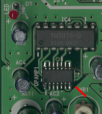
- Potentiometer VR1
Stereo PCB Wiring
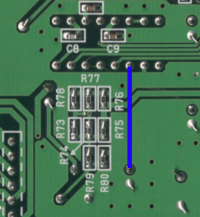
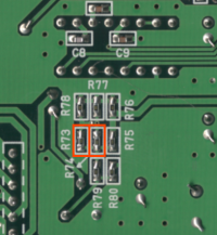
- Remove resistors R73 and R74 as shown in the image below.
- Mount the PCB somewhere, such as on top of a chip with a double sided adhesive pad.
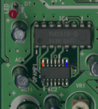
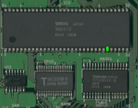
- Solder pin 14 (red in image below) of the C844G (OPAMP1) to the
R Inpad on the stereo PCB. - Solder pin 8 (blue in image below) of the C844G (OPAMP1) to the
L Inpad on the stereo PCB. - Solder pin 27 of the YM2610 chip to the
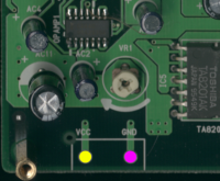
Mix Inpad on the stereo PCB. - Solder the VCC (yellow in image below) and GND (pink in image below) to the VCC and GND pins on the stereo PCB.
- Wire the
L OutandR Outpads of the stereo PCB directly to RCA output jacks or another output port.
Controllers
Neo Geo CD controllers will need a DB15 male connector on the console side and M3 screws and nuts to mount them. It's recommended to get ones with solder cups for easier soldering. Solder one side of the wires to the port. Mount the port, then solder the other side of the wires to the JAMMA edge pads or pins.
Optionally, connect one of the buttons also to the Coin button and this will insert a coin every time that button is pressed — assuming you are not running it in free-play mode. Note that connection to one +5V and one GND is required.
