Master System:Audio Line Out Mod: Difference between revisions
No edit summary |
No edit summary |
||
| (5 intermediate revisions by 2 users not shown) | |||
| Line 1: | Line 1: | ||
This page shows how to get audio directly from the Sega Master System's A/V port. This would most commonly be used for routing audio through the [https://www.ic2005.com/shop/product.php?productid=130 NEO Sega MKIII flash cart], which adds FM audio capability to the SMS via audio mixing jacks. It is a fairly simple modification that involves tapping the audio from the DIN jack and routing it to a separate cable or connector. This modification is also useful for those who want to run their audio separately in order to reduce crosstalk and interference from substandard RGB SCART cables. | This page shows how to get audio directly from the Sega Master System's A/V port. This would most commonly be used for routing audio through the [https://www.ic2005.com/shop/product.php?productid=130 NEO Sega MKIII flash cart], which adds FM audio capability to the SMS via audio mixing jacks. It is a fairly simple modification that involves tapping the audio from the DIN jack and routing it to a separate cable or connector. This modification is also useful for those who want to run their audio separately in order to reduce crosstalk and interference from substandard RGB SCART cables. | ||
== Required Materials == | |||
=Required | |||
* Soldering iron | * Soldering iron | ||
* Leaded solder | * Leaded solder | ||
| Line 13: | Line 10: | ||
* Male RCA cable (for no-cut install) | * Male RCA cable (for no-cut install) | ||
== Standard Install == | |||
=Standard | |||
# Begin by completely disassembling the Sega Master System console using a Phillips head screwdriver. Place the bottom half of the console and motherboard aside for the time being. | # Begin by completely disassembling the Sega Master System console using a Phillips head screwdriver. Place the bottom half of the console and motherboard aside for the time being. | ||
# Determine the best position for your audio jack on the top shell so it does not interfere with the RF shielding or any other components during reassembly. Drill a pilot hole using a small drill bit and then use a step bit to get the appropriate size hole. | # Determine the best position for your audio jack on the top shell so it does not interfere with the RF shielding or any other components during reassembly. Drill a pilot hole using a small drill bit and then use a step bit to get the appropriate size hole. | ||
| Line 20: | Line 16: | ||
# Mount the audio connector to the hole drilled earlier and tighten the outer nut so the connector does not move. Use a 3.5 mm audio cable to ensure that there is zero movement in the connector. | # Mount the audio connector to the hole drilled earlier and tighten the outer nut so the connector does not move. Use a 3.5 mm audio cable to ensure that there is zero movement in the connector. | ||
# Solder the other ends of the wires to the appropriate pins on the DIN jack as shown here. Audio is on the left pin and ground is on the right: | # Solder the other ends of the wires to the appropriate pins on the DIN jack as shown here. Audio is on the left pin and ground is on the right: | ||
# | #: [[File:SMSAudio03.jpg]] | ||
# Reassemble the console, taking care to route the wires so that they do not interfere with the RF shielding or other components. | # Reassemble the console, taking care to route the wires so that they do not interfere with the RF shielding or other components. | ||
== No-cut Install == | |||
=No-cut | |||
# Begin by completely disassembling the console using a Phillips head screwdriver. | # Begin by completely disassembling the console using a Phillips head screwdriver. | ||
# Take a standard RCA cable, strip the end and run it through one of the vents in the bottom shell, in roughly the same area where the A/V connector would be. It is recommended to tie the cable to the plastic as shown below so there is no chance of it accidentally pulling out: | # Take a standard RCA cable, strip the end and run it through one of the vents in the bottom shell, in roughly the same area where the A/V connector would be. It is recommended to tie the cable to the plastic as shown below so there is no chance of it accidentally pulling out: | ||
# | #: [[File:SMSAudio01.jpg]] | ||
# Flip the SMS main board over and line it up with the rear cover (detailed pic of solder points is next): | # Flip the SMS main board over and line it up with the rear cover (detailed pic of solder points is next): | ||
# | #: [[File:SMSAudio02.jpg]] | ||
# Strip the wires on the cut-off end of the RCA cable and tin the ends. | # Strip the wires on the cut-off end of the RCA cable and tin the ends. | ||
# Place a piece of non-conductive tape underneath the area where the wires then solder to the following points on the board. As before, audio is on the left and ground is on the right: | # Place a piece of non-conductive tape underneath the area where the wires then solder to the following points on the board. As before, audio is on the left and ground is on the right: | ||
# | #: [[File:SMSAudio03.jpg]] | ||
# Ensure that the soldered wires do not come into contact with the RF shielding and tuck the excess audio wire underneath the shielding. | # Ensure that the soldered wires do not come into contact with the RF shielding and tuck the excess audio wire underneath the shielding. | ||
# Ensure the knot is properly snug against the case as shown below. | # Ensure the knot is properly snug against the case as shown below. | ||
# | #: [[File:SMSAudio04.jpg]] | ||
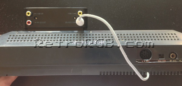
# Reassemble the console and test. If you're using the Neo Sega MKIII, plug the new audio cable into the "SMS AUDIO IN" port as shown below, then run an RCA audio cable from the "FM AUDIO OUT" port of the Neo Sega MKIII into the audio input of your device. | # Reassemble the console and test. If you're using the Neo Sega MKIII, plug the new audio cable into the "SMS AUDIO IN" port as shown below, then run an RCA audio cable from the "FM AUDIO OUT" port of the Neo Sega MKIII into the audio input of your device. | ||
# | #: [[File:SMSAudio05.jpg]] | ||
== RGB Note == | |||
If an RGB cable is used and the input device being used does not have a separate audio input, the audio line can be wired to both pins 2 and 6 on the SCART connector, then audio ground to pin 4, following the pinout shown below: | |||
[[File:SMSAudio06.jpg]] | [[File:SMSAudio06.jpg]] | ||
[[Category:Master System]] | |||
[[Category:Audio Mods]] | |||
Latest revision as of 01:24, 5 June 2024
This page shows how to get audio directly from the Sega Master System's A/V port. This would most commonly be used for routing audio through the NEO Sega MKIII flash cart, which adds FM audio capability to the SMS via audio mixing jacks. It is a fairly simple modification that involves tapping the audio from the DIN jack and routing it to a separate cable or connector. This modification is also useful for those who want to run their audio separately in order to reduce crosstalk and interference from substandard RGB SCART cables.
Required Materials
- Soldering iron
- Leaded solder
- Wire cutters and stripper
- Wire
- Drill with step bit (for standard install)
- Female 3.5 mm audio connector (for standard install)
- Male RCA cable (for no-cut install)
Standard Install
- Begin by completely disassembling the Sega Master System console using a Phillips head screwdriver. Place the bottom half of the console and motherboard aside for the time being.
- Determine the best position for your audio jack on the top shell so it does not interfere with the RF shielding or any other components during reassembly. Drill a pilot hole using a small drill bit and then use a step bit to get the appropriate size hole.
- Take a female 3.5 mm audio connector and begin wiring it up. Because the Master System only has mono audio, only two wires are required (audio and ground). Cut the wires to an appropriate length so that the console halves can be easily separated for future modifications or repairs, but not excessively long as this can potentially generate interference.
- Mount the audio connector to the hole drilled earlier and tighten the outer nut so the connector does not move. Use a 3.5 mm audio cable to ensure that there is zero movement in the connector.
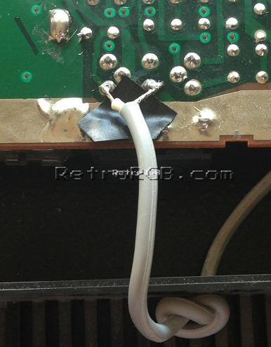
- Solder the other ends of the wires to the appropriate pins on the DIN jack as shown here. Audio is on the left pin and ground is on the right:
- Reassemble the console, taking care to route the wires so that they do not interfere with the RF shielding or other components.
No-cut Install
- Begin by completely disassembling the console using a Phillips head screwdriver.
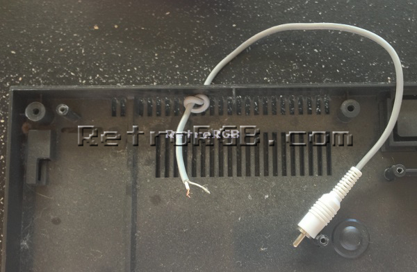
- Take a standard RCA cable, strip the end and run it through one of the vents in the bottom shell, in roughly the same area where the A/V connector would be. It is recommended to tie the cable to the plastic as shown below so there is no chance of it accidentally pulling out:
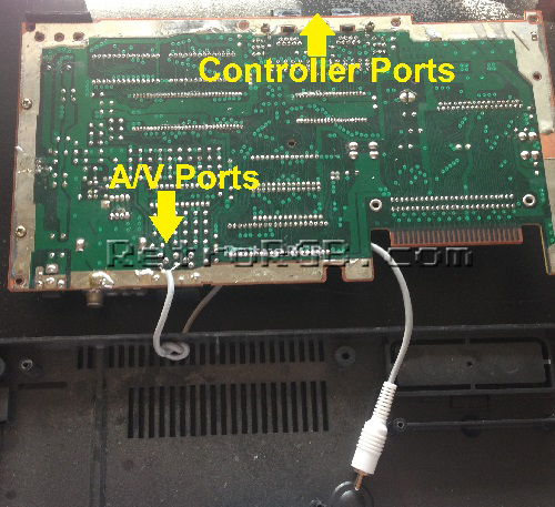
- Flip the SMS main board over and line it up with the rear cover (detailed pic of solder points is next):
- Strip the wires on the cut-off end of the RCA cable and tin the ends.
- Place a piece of non-conductive tape underneath the area where the wires then solder to the following points on the board. As before, audio is on the left and ground is on the right:
- Ensure that the soldered wires do not come into contact with the RF shielding and tuck the excess audio wire underneath the shielding.
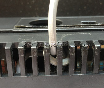
- Ensure the knot is properly snug against the case as shown below.
- Reassemble the console and test. If you're using the Neo Sega MKIII, plug the new audio cable into the "SMS AUDIO IN" port as shown below, then run an RCA audio cable from the "FM AUDIO OUT" port of the Neo Sega MKIII into the audio input of your device.
RGB Note
If an RGB cable is used and the input device being used does not have a separate audio input, the audio line can be wired to both pins 2 and 6 on the SCART connector, then audio ground to pin 4, following the pinout shown below:
