Neo Geo:RGB Bypass Mod (AES): Difference between revisions
m (→RGB Bypass) |
No edit summary |
||
| (3 intermediate revisions by the same user not shown) | |||
| Line 1: | Line 1: | ||
This page will show you a "basic" bypass for the Neo Geo AES console that eliminates the Sony CXA amp and sends video (at the proper | This page will show you a "basic" RGB bypass for the Neo Geo AES console that eliminates the Sony CXA amp and sends RGBS video (at the proper voltages) directly from the NG's digital-to-analog-converter, to the multi-out. The method shown here will work on any Neo Geo revision, but care must be taken when deciding what points to solder to as the traces change between revisions. It's been long discussed that some Neo Geo units output better RGB video than others. While that's true, all AES' can have a fairly simple RGB bypass performed that gets the best out of the built-in DAC. That means you can make every revision AES look identical, regardless of serial number. This modification is also strongly recommended if you plan on feeding RGB output to any RetroTink device. | ||
== Comparisons == | == Comparisons == | ||
| Line 13: | Line 11: | ||
== Installation == | == Installation == | ||
The images in this guide show the process for the 3-6 revision of the Neo Geo. | The images in this guide show the process for the 3-6 revision of the Neo Geo. But care must be taken when doing this on other systems. | ||
=== Tools Needed === | === Tools Needed === | ||
| Line 20: | Line 18: | ||
* Soldering iron, wire, heatshrink tubing | * Soldering iron, wire, heatshrink tubing | ||
* [https://www.digikey.com/product-detail/en/vishay-bc-components/MBB02070C1500FCT00/BC3614CT-ND/7351044 150 Ohm resistors] | * [https://www.digikey.com/product-detail/en/vishay-bc-components/MBB02070C1500FCT00/BC3614CT-ND/7351044 150 Ohm resistors] | ||
* 75 Ohm resistor(s) | |||
* 470uF 16V electrolytic capacitor(s) (220uF to 470uF are valid ranges if you don't have 470uF) | |||
* Desoldering gun not necessary, but might make it easier | * Desoldering gun not necessary, but might make it easier | ||
| Line 32: | Line 32: | ||
# Remove the reset button and power switch, then carefully lift the motherboard out of the bottom case. | # Remove the reset button and power switch, then carefully lift the motherboard out of the bottom case. | ||
=== RGB Bypass === | === AV Connector output=== | ||
You can refer to the AV connector pinout (as documented Neo Geo [https://wiki.neogeodev.org/index.php?title=Pinouts Dev wiki]) to validate the pinout. All Neo Geo consoles should use the same 8 pin DIN for AV output. Newer consoles connect the composite video and CSYNC pins together and only output composite video. For optimal RGB output, this mod will also do a CSYNC restore on these consoles. | |||
===Neo Geo RGB Amp=== | |||
The Neo Geo AES uses the CXA1145 RGB amp. More information about this amp, and more importantly, the pinout can be found [https://wiki.console5.com/wiki/CXA1145 here]. Refer to the pinout when reviewing the rest of the modification below. | |||
===RGB Bypass=== | |||
Here's a quick overview of the entire mod you'll be doing, as seen from both the top and underside of the console. This is a rev 3-5 PCB but yours will be very similar. Click on the images to see a bigger image with more details. | |||
[[File:Top.png|none|thumb|800x800px]] | |||
[[File:Bottom.png|none|thumb|800x800px]] | |||
The traces going between the stock RGB amp (CXA1145) and the AV output port might differ between releases, but the pinout on the amp is the same. The instructions shown here are more focused on 3-5/3-6 PCBs but they can easily be modified to work with older Neo Geo AES PCB revisions once the basic concept is understood. The 2 most confusing parts are where you pickup the RGB signals for the output and how to handle composite video and CSYNC. | |||
#Verify that the RGB and composite video capacitors on to the top side of the motherboard are 470uF 16V capacitors. If they are not, replaced them. (they are the 4 with the hot glue in the image) | |||
#On the underside, cut the trace going between the positive pin of the 4 capacitors and the corresponding RGB and composite video pins of the CXA1145 amp (pins 23,22,21 and 20). | |||
#Remove the 3 resistors that sit between the RGB capacitors and multiAV port. On 3-5/3-6 systems, these will be 75 ohm resistors. On older AES PCBs, these will be 68 ohm. If your system uses 68 ohm resistors, remove all 5 of them (3 for RGB, 1 for CSYNC, 1 for composite video) You can easily tell what resistor does what by using a multimeter between one of the resistor legs and the AV port in the back in diode or continuity mode. | |||
#Install 3 150 ohm resistors where the old RGB resistors were that you just removed. If you also removed 68 ohm resistors that used to be composite video and csync, replace them with 75 ohm resistor(s). | |||
#Next is the most confusing part of the RGB mod as it is dependent on what AES revision you have, and every revision is slightly different. You need to connect the RGB signals from the DAC to the positive side of the capacitors from step 1 above. This is where the RGB signals is fed back to the AV output connector, bypassing the CXA1145. In the image above, you can see how we determined the RGB spots. Do the same on your PCB, start at the RGB input pins on the CXA1145 and work backwards until you reach the DAC. Solder wire from the RGB-DAC pins to the positive pin of the 470uF capacitor that corresponds to that color. Repeat this for all 3 RGB lines. | |||
===CSYNC Restore=== | |||
On newer AES PCBs, CSYNC and composite video is connected together and only composite video signal is output on both pins of the AV connector. You need to see if that's the case on your PCB and cut the trace that connects them (see example above showing this) Now that the signals are separate, it's time to restore the CSYNC signal. The assumption here is that you know what is the CSYNC output pin (see image above) and there's already a 75 ohm resistor connecting to it, and it connects to a 470uF capacitor which currently has it's positive leg disconnected from the CXA1145. | |||
#Restore the CSYNC signal by connecting a wire from pin 10 of the CXA1145 chip to the positive pin of the CSYNC 470uF capacitor. If you did this correctly, you'll have CXA1145 pin 10 -> wire -> 470uF capacitor -> 75 ohm resistor -> AV port. | |||
===Composite Video Restore=== | |||
On older AES PCBs, there should be 1 more capacitor and resistor left for composite video. Confirm that the capacitor is 470uF and the resistor is 75 ohm. The positive leg of this capacitor should be connected to pin 20 of the CXA1145. If you have a newer AES PCB, you must build this circuit to handle composite video. The best spot to do this is right on top of the CXA1145. | |||
#Connect the positive leg of a 470uF 16V capacitor to pin 20 of the CXA1145 | |||
#Connect a 75 ohm resistor to the negative leg of this capacitor | |||
#Run wire from the other side of the 75 ohm resistor to the ferrite bead that connects to the composite video output pin of the AV port | |||
=== End Result === | |||
Congrats. You're done. The CXA1145 RGB amp is now bypassed for RGBS but is still used for composite video generation. Your Neo Geo PCB should look like something similar to the image below. You can use a Sega Genesis 1 AV cable to test composite video output. | |||
Here's a few other items you can tackle while you're here: | |||
# Plug headphones to the front audio port. Load the 240p test suite (if you have a multicart that allows you to run it) and validate the stereo output. Some 3-6 PCBs have LEFT/RIGHT reversed. | |||
# Cut the centre post of the top plastic shell off! Any pressure on the top lid will cause that post to go right through the PCB. It serves no purpose beyond a disaster waiting to happen. | |||
[[File:Bottom after.png|none|thumb|600x600px]] | |||
[[File:Top after.png|none|thumb|600x600px]] | |||
Latest revision as of 01:34, 9 October 2024
This page will show you a "basic" RGB bypass for the Neo Geo AES console that eliminates the Sony CXA amp and sends RGBS video (at the proper voltages) directly from the NG's digital-to-analog-converter, to the multi-out. The method shown here will work on any Neo Geo revision, but care must be taken when deciding what points to solder to as the traces change between revisions. It's been long discussed that some Neo Geo units output better RGB video than others. While that's true, all AES' can have a fairly simple RGB bypass performed that gets the best out of the built-in DAC. That means you can make every revision AES look identical, regardless of serial number. This modification is also strongly recommended if you plan on feeding RGB output to any RetroTink device.
Comparisons
- Video comparison:
- SMPTE color bar comparison (click for full screen):
- Oscilloscope analysis (RetroRGB)
Installation
The images in this guide show the process for the 3-6 revision of the Neo Geo. But care must be taken when doing this on other systems.
Tools Needed
- Basic soldering skills
- Soldering iron, wire, heatshrink tubing
- 150 Ohm resistors
- 75 Ohm resistor(s)
- 470uF 16V electrolytic capacitor(s) (220uF to 470uF are valid ranges if you don't have 470uF)
- Desoldering gun not necessary, but might make it easier
Disassembly
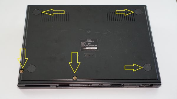
- Remove the screws on the bottom of the AES. There are three under the marked footpads in the image below. Please note that the screws are different sizes, so make sure to mark where each goes!
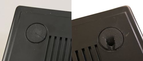
- Unfortunately, due to the age of these footpads, they'll most likely break. If you get lucky, you can peel them back just enough to get your screwdriver in, but expect to accidentally break at least one:
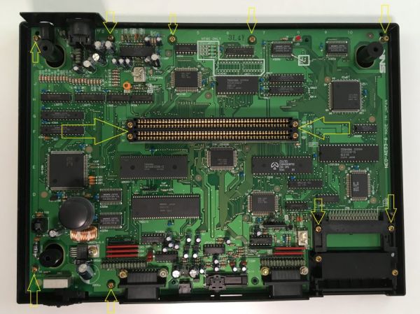
- After removing the top plastic cover, remove the following screws from the motherboard.
- Remove the reset button and power switch, then carefully lift the motherboard out of the bottom case.
AV Connector output
You can refer to the AV connector pinout (as documented Neo Geo Dev wiki) to validate the pinout. All Neo Geo consoles should use the same 8 pin DIN for AV output. Newer consoles connect the composite video and CSYNC pins together and only output composite video. For optimal RGB output, this mod will also do a CSYNC restore on these consoles.
Neo Geo RGB Amp
The Neo Geo AES uses the CXA1145 RGB amp. More information about this amp, and more importantly, the pinout can be found here. Refer to the pinout when reviewing the rest of the modification below.
RGB Bypass
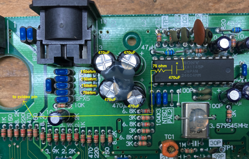
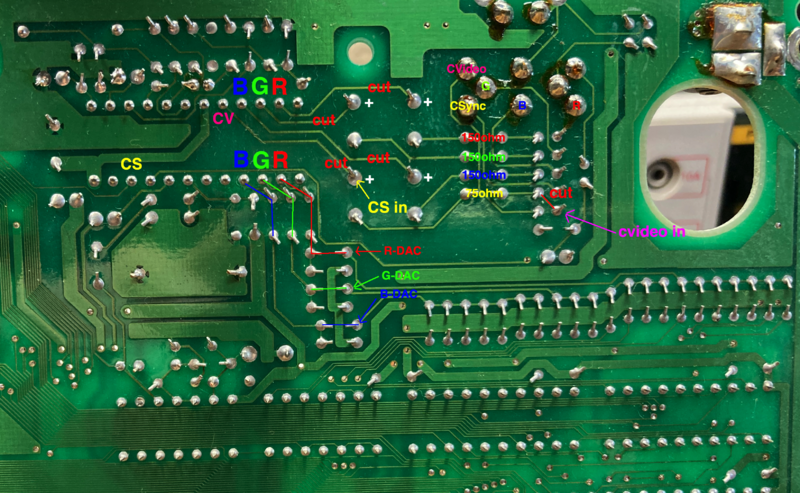
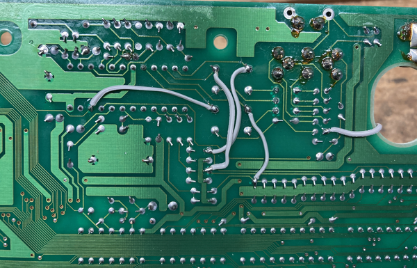
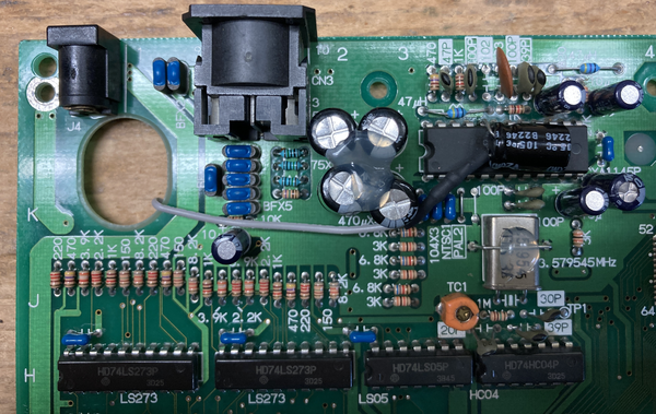
Here's a quick overview of the entire mod you'll be doing, as seen from both the top and underside of the console. This is a rev 3-5 PCB but yours will be very similar. Click on the images to see a bigger image with more details.
The traces going between the stock RGB amp (CXA1145) and the AV output port might differ between releases, but the pinout on the amp is the same. The instructions shown here are more focused on 3-5/3-6 PCBs but they can easily be modified to work with older Neo Geo AES PCB revisions once the basic concept is understood. The 2 most confusing parts are where you pickup the RGB signals for the output and how to handle composite video and CSYNC.
- Verify that the RGB and composite video capacitors on to the top side of the motherboard are 470uF 16V capacitors. If they are not, replaced them. (they are the 4 with the hot glue in the image)
- On the underside, cut the trace going between the positive pin of the 4 capacitors and the corresponding RGB and composite video pins of the CXA1145 amp (pins 23,22,21 and 20).
- Remove the 3 resistors that sit between the RGB capacitors and multiAV port. On 3-5/3-6 systems, these will be 75 ohm resistors. On older AES PCBs, these will be 68 ohm. If your system uses 68 ohm resistors, remove all 5 of them (3 for RGB, 1 for CSYNC, 1 for composite video) You can easily tell what resistor does what by using a multimeter between one of the resistor legs and the AV port in the back in diode or continuity mode.
- Install 3 150 ohm resistors where the old RGB resistors were that you just removed. If you also removed 68 ohm resistors that used to be composite video and csync, replace them with 75 ohm resistor(s).
- Next is the most confusing part of the RGB mod as it is dependent on what AES revision you have, and every revision is slightly different. You need to connect the RGB signals from the DAC to the positive side of the capacitors from step 1 above. This is where the RGB signals is fed back to the AV output connector, bypassing the CXA1145. In the image above, you can see how we determined the RGB spots. Do the same on your PCB, start at the RGB input pins on the CXA1145 and work backwards until you reach the DAC. Solder wire from the RGB-DAC pins to the positive pin of the 470uF capacitor that corresponds to that color. Repeat this for all 3 RGB lines.
CSYNC Restore
On newer AES PCBs, CSYNC and composite video is connected together and only composite video signal is output on both pins of the AV connector. You need to see if that's the case on your PCB and cut the trace that connects them (see example above showing this) Now that the signals are separate, it's time to restore the CSYNC signal. The assumption here is that you know what is the CSYNC output pin (see image above) and there's already a 75 ohm resistor connecting to it, and it connects to a 470uF capacitor which currently has it's positive leg disconnected from the CXA1145.
- Restore the CSYNC signal by connecting a wire from pin 10 of the CXA1145 chip to the positive pin of the CSYNC 470uF capacitor. If you did this correctly, you'll have CXA1145 pin 10 -> wire -> 470uF capacitor -> 75 ohm resistor -> AV port.
Composite Video Restore
On older AES PCBs, there should be 1 more capacitor and resistor left for composite video. Confirm that the capacitor is 470uF and the resistor is 75 ohm. The positive leg of this capacitor should be connected to pin 20 of the CXA1145. If you have a newer AES PCB, you must build this circuit to handle composite video. The best spot to do this is right on top of the CXA1145.
- Connect the positive leg of a 470uF 16V capacitor to pin 20 of the CXA1145
- Connect a 75 ohm resistor to the negative leg of this capacitor
- Run wire from the other side of the 75 ohm resistor to the ferrite bead that connects to the composite video output pin of the AV port
End Result
Congrats. You're done. The CXA1145 RGB amp is now bypassed for RGBS but is still used for composite video generation. Your Neo Geo PCB should look like something similar to the image below. You can use a Sega Genesis 1 AV cable to test composite video output.
Here's a few other items you can tackle while you're here:
- Plug headphones to the front audio port. Load the 240p test suite (if you have a multicart that allows you to run it) and validate the stereo output. Some 3-6 PCBs have LEFT/RIGHT reversed.
- Cut the centre post of the top plastic shell off! Any pressure on the top lid will cause that post to go right through the PCB. It serves no purpose beyond a disaster waiting to happen.

