Dreamcast:Digital Audio (SPDIF) Mod: Difference between revisions
Jump to navigation
Jump to search
mNo edit summary |
mNo edit summary |
||
| (6 intermediate revisions by the same user not shown) | |||
| Line 1: | Line 1: | ||
[[File:Dreamcast_SPDIF_Mod_3.jpg|thumb|Example completed install.]] | |||
Original guide adapted from a [https://web.archive.org/web/20170626072614/https://www.assemblergames.com/threads/saturn-dreamcast-toslink.57670/ post by citrus3000psi]. | Original guide adapted from a [https://web.archive.org/web/20170626072614/https://www.assemblergames.com/threads/saturn-dreamcast-toslink.57670/ post by citrus3000psi]. | ||
| Line 6: | Line 7: | ||
* [https://oshpark.com/shared_projects/kvtStGOq Pep Audio 1.2 PCB] | * [https://oshpark.com/shared_projects/kvtStGOq Pep Audio 1.2 PCB] | ||
* If using TOSLINK: | |||
** TX178A (TOSLINK port) | |||
** [https://oshpark.com/shared_projects/b9Fjt84V TOSLINK PCB by citrus3000psi]. | |||
* If not using a TOSLINK port, you will need your own jack. | |||
== Installation == | == Installation == | ||
# On the top of the motherboard, solder wires from these | # There exists an issue (as noted by [https://shmups.system11.org/viewtopic.php?p=1425441&sid=e4913934cbae57d52de7db492efe8d16#p1425441 FireBrandX]) with the Pep Audio PCB where some of the boards have extra ground fill in front of the pins and cause shorts. Use a multimeter to make sure none of the pads (GND excluded) have continuity to GND. If you do find continuity, you will need to use a hobby knife to cut off the area marked in red below: | ||
#* [[File:Saturn SPDIF Mod 6.jpg|400px]] | |||
# Assemble the Pep Audio PCB. | |||
# Bridge the "SAT" pad on the Pep Audio PCB to the pad next to it (although it's for Saturn, it's the same setting for Dreamcast). | |||
# On the top of the motherboard, solder wires from these legs on the DAC to the matching pads on the Pep Audio board. | |||
## `DATA` on motherboard to `DAT` on Pep Audio PCB ('''not''' `DATA`!). | ## `DATA` on motherboard to `DAT` on Pep Audio PCB ('''not''' `DATA`!). | ||
## `BCK` on motherboard to `BC` on Pep Audio PCB. | ## `BCK` on motherboard to `BC` on Pep Audio PCB. | ||
| Line 17: | Line 26: | ||
## `GND` on motherboard to `GND` on Pep Audio PCB. | ## `GND` on motherboard to `GND` on Pep Audio PCB. | ||
#: [[File:Dreamcast_SPDIF_Mod_1.jpg|400px]] | #: [[File:Dreamcast_SPDIF_Mod_1.jpg|400px]] | ||
# Connect the output jack: | |||
#* If using a TOSLINK port, connect +5V and GND to it. Also connect `DATA` ('''not''' `DAT`!) on the Pep Audio PCB to the `In` on the TOSLINK PCB. | |||
#* If using your own SPDIF port, connect `DATA` on the Pep Audio PCB to the data pin and GND to GND. | |||
# Partially reassemble, snaking the board past the metal shield as shown below: | # Partially reassemble, snaking the board past the metal shield as shown below: | ||
#: [[File:Dreamcast_SPDIF_Mod_2.jpg|400px]] | #: [[File:Dreamcast_SPDIF_Mod_2.jpg|400px]] | ||
# | # Mount the output jack on the case. | ||
Latest revision as of 16:23, 15 July 2023
Original guide adapted from a post by citrus3000psi.
This guide assumes the DAC in your Dreamcast is a PCM1725.
Required Materials
- Pep Audio 1.2 PCB
- If using TOSLINK:
- TX178A (TOSLINK port)
- TOSLINK PCB by citrus3000psi.
- If not using a TOSLINK port, you will need your own jack.
Installation
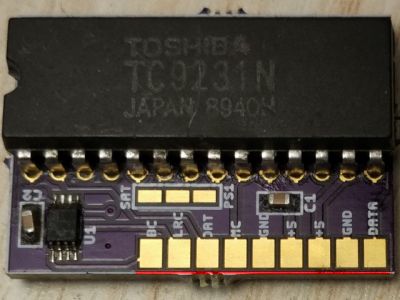
- There exists an issue (as noted by FireBrandX) with the Pep Audio PCB where some of the boards have extra ground fill in front of the pins and cause shorts. Use a multimeter to make sure none of the pads (GND excluded) have continuity to GND. If you do find continuity, you will need to use a hobby knife to cut off the area marked in red below:
- Assemble the Pep Audio PCB.
- Bridge the "SAT" pad on the Pep Audio PCB to the pad next to it (although it's for Saturn, it's the same setting for Dreamcast).
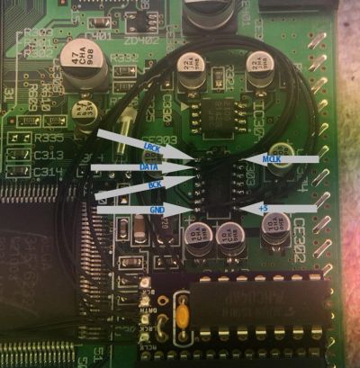
- On the top of the motherboard, solder wires from these legs on the DAC to the matching pads on the Pep Audio board.
DATAon motherboard toDATon Pep Audio PCB (notDATA!).BCKon motherboard toBCon Pep Audio PCB.LRCKon motherboard toLRCon Pep Audio PCB.MCLKon motherboard toMCon Pep Audio PCB.+5on motherboard to5Von Pep Audio PCB.GNDon motherboard toGNDon Pep Audio PCB.
- Connect the output jack:
- If using a TOSLINK port, connect +5V and GND to it. Also connect
DATA(notDAT!) on the Pep Audio PCB to theInon the TOSLINK PCB. - If using your own SPDIF port, connect
DATAon the Pep Audio PCB to the data pin and GND to GND.
- If using a TOSLINK port, connect +5V and GND to it. Also connect
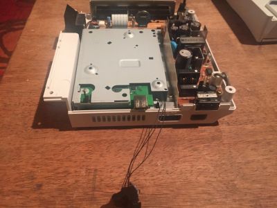
- Partially reassemble, snaking the board past the metal shield as shown below:
- Mount the output jack on the case.


