Master System:RGB Bypass Mod: Difference between revisions
No edit summary |
No edit summary |
||
| (10 intermediate revisions by 4 users not shown) | |||
| Line 1: | Line 1: | ||
[[Category: | [[Category:Master System]] | ||
{{Note|The SMS 1 does not require a modification for RGB output. It only needs a cable. NTSC and PAL SMS II consoles require a mod, but a "bypass" isn't required, you just need to add an output jack and wire up the RGB output.}} | |||
[[File:SMSRGBBypassCompare.jpg]] | |||
This procedure shows how to bypass the Master System's pre-existing amplified RGB output. All details are below, but this mod requires you to make irreversible modifications to your system. As a result, this mod is not recommended for beginners. | |||
== Why perform an RGB bypass? == | |||
There are three primary reasons someone might want to perform this modification: | |||
** | * '''Jailbar fix''': As shown in the picture below, performing this bypass removes most (but not all) jailbars from Sega Master System consoles. Please note that there are many different ways to reduce jailbars and doing an RGB bypass is just one method. <br> [[File:SMSRGBBypassCompareZoom.png]] | ||
There are | * '''New RGB Amp''': Most SMS systems use a Sony CXA1145 video encoder chip to amplify the RGB signal while others use a pin-compatible Fujitsu MB3514 or the older Sony V7040. The CXA1145 is an excellent chip, however, this bypass uses the newer Texas Instruments THS7314, which has a high-quality low-pass filter that removes unwanted noise. Using the THS7314 isn't a clear "better or worse" choice, it's mainly a preference. Some might argue that the "ringing" the CXA1145 produces creates the specific look of the SMS that shouldn't be changed. | ||
* '''SMS RGB issues''': Some people run into issues with the stock SMS RGB the multi-out.There are a few solutions for this, but performing this bypass will guarantee that your SMS will be compatible with all RGB setups. | |||
An RGB bypass may also be beneficial for French SMSes, as this will allow them to use RGB cables intended for standard SMS consoles instead of the "Adapteur R.V.B." cable they originally came with. | |||
== Installation == | |||
Here are instructions on installing a bypass in an SMS 1. You can follow the same instructions for an SMS 2, however since there's no multi-out, you'll need to mount your own. | |||
** | === Materials and Tools === | ||
* RGB bypass board | |||
* JIS or Phillips head screwdriver | |||
* Soldering iron | |||
* Leaded solder | |||
* Thin gauge wire | |||
* Flush cutters | |||
* Razor blade | |||
* Small pick or dental tool for lifting chip pins | |||
* Desoldering braid or desoldering gun | |||
* Multimeter | |||
=== Determine your Output Solution === | |||
{{Note|If you plan on using a custom output connector, you can skip this entire section and go right to "removing the RF module".}} | |||
==== (Option 1) Sever RGBS to the Multi-Out ==== | |||
If you're using the stock multi-out, you'll need to sever the existing RGB lines on the board. If you're using any other output connector (or have an SMS 2) you can skip this. | |||
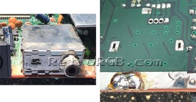
# It's recommended to cut the traces underneath the multi-out on the bottom of the motherboard to ensure the RGBs signals are no longer connected. Test that continuity is broken using a multimeter. <br> [[File:SMSRGBbypassCutTraces.jpg|400px]] | |||
#* Alternatively, if you have a motherboard that connects directly from the CXA1145 to the multi-out (most NTSC's do), you can cut or lift the CXA pins. Also, if you have an MK-2000, you can try lifting components between. | |||
==== (Option 2) Removing Unneeded Components from the Bypass Board ==== | |||
If you plan on using the stock multi-out, or another multi-out that uses Genesis / SMS RGB cables ([https://www.digikey.com/product-detail/en/MD-90SN/CP-2590-ND/352878 such as a Genesis 2 connector]), you'll need to remove components on the RGB Bypass board: | |||
: | * '''RGB Capacitors''': If you're using a stock SMS / Genesis cable, you'll need to remove the RGB capacitors on the board. You can then connect RGB on the multi-out to the "input" side of the capacitor pads. Alternatively, you can remove the caps and just solder directly to the THS7314. | ||
* '''Csync''': As always, with SMS and Genesis, CSYNC can be problematic. You can either use sync the way it was designed on this board, or use luma as sync. If needed, you can connect a sync stripper to either solution: | |||
** If you'd like to use luma as sync, just solder a wire from [http://console5.com/wiki/CXA1145 pin 16 on the Sony CXA1154 chip] to CSI on the bypass board. | |||
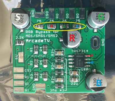
** Whether you decide to use CSYNC or luma as sync, connect the "CSO" pad to the multi out. Then if you have issues after installation, you can remove the components one by one until the signal works properly: <br> [[File:GenesisBypassBoardComponentRemoval.jpg|400px]] | |||
: | |||
: [[File: | |||
=== Removing the RF Modulator === | |||
# Completely disassemble your console, including the heat sink. Flip the motherboard over and de-solder the RF modulator. You'll need to be patient, use a desoldering gun and some desoldering braid if possible. Be very careful not to damage the motherboard when removing it. Also, make sure the solder pads are very clean on both the top and bottom of where the RF modulator used to sit: <br> [[File:SMSRGBbypassRFRemoval.jpg|400px]] | |||
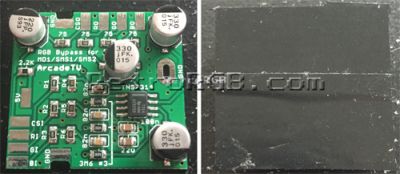
# Add some non-conductive tape such as Kapton tape to the bottom of the RGB bypass board: <br> [[File:GenesisRGBBypass06.jpg|400px]] | |||
# Position the board where the RF modulator used to sit as shown below. You'll then want to run thick wire through the three ground holes, then bend and solder them on each end. Also, connect a small wire to the 5V hole on the RF adapter's mounting hole. Double check with a multimeter that it's the correct 5V location: <br> [[File:SMSRGBbypassBoardInstall.jpg|400px]] | |||
=== Tapping RGBS from the VDP === | |||
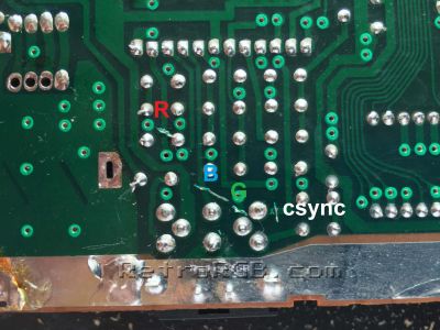
# Locate the Sega 315-5124 chip on your board. Tin the red, green, blue and composite sync pins (26, 27, 28 & 29, respectively), as well as the inputs on the bypass board and connect the two. <br> [[File:Sega315-5124.jpg|400px]] | |||
# Connect the RGB to the multi-out. It may be preferable to solder to the top of the multi-out to keep the wires from getting pinched. The picture below shows the bypass board with the capacitors removed (for use with stock SMS cables) and RGB-out coming directly from the chip (the B&G wires aren't connected, as they would have blocked the view in the picture). | |||
#* Please note that if you're using a different output connector, you'll also need to connect ground and possibly 5V. <br> [[File:SMSRGBbypassTopOfMultiOut.jpg|400px]] | |||
#* Alternatively, you can solder directly to the pins on the bottom of the DIN connector. (composite video pin is just shown for reference): <br> [[File:SMSRGBbypassMultiOutPins.jpg|400px]] | |||
=== French Consoles === | |||
All French Master System consoles, including the Master System II, ''only'' have RGB output, but it is neither amplified or buffered, and so these systems require the use of a special RGB cable. Performing an RGB bypass on these is fairly easy since they lack a video encoder and wire up the RGB output directly from the VDP using either bodge wires or jumper links. | |||
# On the French model 1, there will be three bodge wires connecting the RGB signals from the VDP to where the output pins on the video encoder would be. Desolder these wires from the video encoder vias and make note of what wire belongs to what signal. They can be denoted based on the resistor footprint at the other end of the wire: | |||
#* R6: Red | |||
#* R7: Green | |||
#* R8: Blue | |||
#* Composite sync can be taken from where R19 connects to the DIN connector. | |||
# Place the bypass board where the RF modulator would normally sit, as per the "Removing the RF Modulator" procedure above. | |||
# Connect the existing bodge wires to the RGB input pads on the bypass board, then connect the output wires from the bypass to the vias for the video encoder output pins. | |||
For the French SMS II, the procedure is similar but involves removing jumper links instead of wires. | |||
# Desolder the jumper links for red, green and blue. They are labeled on the board as "JPR", "JPG" and "JPB" respectively. | |||
# Place the bypass board where the RF modulator would normally sit, as per the "Removing the RF Modulator" procedure above. | |||
# Solder wires from the rightmost vias on JPB and JPG and the front-facing via of JPR to the blue, green and red input pads of the bypass board. | |||
# Solder wires from the leftmost vias on JPB and JPG and the rear-facing via of JPR to the blue, green and red output pads of the bypass board. | |||
== Troubleshooting == | |||
* If the screen is too dark, your RGB cable most likely has 75 ohm resistors in the console side of the cable. If that's the case, simply remove the resistors on the bypass board and bridge the connections (as shown in the above picture). | |||
* There will always be ''some'' noise or jailbars on SMS consoles, but after performing the mod, it should be greatly improved. | |||
[[Category:Master System]] | |||
[[Category:Video Mods]] | |||
Latest revision as of 18:14, 4 June 2024
| The SMS 1 does not require a modification for RGB output. It only needs a cable. NTSC and PAL SMS II consoles require a mod, but a "bypass" isn't required, you just need to add an output jack and wire up the RGB output. |

This procedure shows how to bypass the Master System's pre-existing amplified RGB output. All details are below, but this mod requires you to make irreversible modifications to your system. As a result, this mod is not recommended for beginners.
Why perform an RGB bypass?
There are three primary reasons someone might want to perform this modification:
- Jailbar fix: As shown in the picture below, performing this bypass removes most (but not all) jailbars from Sega Master System consoles. Please note that there are many different ways to reduce jailbars and doing an RGB bypass is just one method.

- New RGB Amp: Most SMS systems use a Sony CXA1145 video encoder chip to amplify the RGB signal while others use a pin-compatible Fujitsu MB3514 or the older Sony V7040. The CXA1145 is an excellent chip, however, this bypass uses the newer Texas Instruments THS7314, which has a high-quality low-pass filter that removes unwanted noise. Using the THS7314 isn't a clear "better or worse" choice, it's mainly a preference. Some might argue that the "ringing" the CXA1145 produces creates the specific look of the SMS that shouldn't be changed.
- SMS RGB issues: Some people run into issues with the stock SMS RGB the multi-out.There are a few solutions for this, but performing this bypass will guarantee that your SMS will be compatible with all RGB setups.

An RGB bypass may also be beneficial for French SMSes, as this will allow them to use RGB cables intended for standard SMS consoles instead of the "Adapteur R.V.B." cable they originally came with.
Installation
Here are instructions on installing a bypass in an SMS 1. You can follow the same instructions for an SMS 2, however since there's no multi-out, you'll need to mount your own.
Materials and Tools
- RGB bypass board
- JIS or Phillips head screwdriver
- Soldering iron
- Leaded solder
- Thin gauge wire
- Flush cutters
- Razor blade
- Small pick or dental tool for lifting chip pins
- Desoldering braid or desoldering gun
- Multimeter
Determine your Output Solution
| If you plan on using a custom output connector, you can skip this entire section and go right to "removing the RF module". |
(Option 1) Sever RGBS to the Multi-Out
If you're using the stock multi-out, you'll need to sever the existing RGB lines on the board. If you're using any other output connector (or have an SMS 2) you can skip this.
- It's recommended to cut the traces underneath the multi-out on the bottom of the motherboard to ensure the RGBs signals are no longer connected. Test that continuity is broken using a multimeter.
- Alternatively, if you have a motherboard that connects directly from the CXA1145 to the multi-out (most NTSC's do), you can cut or lift the CXA pins. Also, if you have an MK-2000, you can try lifting components between.

(Option 2) Removing Unneeded Components from the Bypass Board
If you plan on using the stock multi-out, or another multi-out that uses Genesis / SMS RGB cables (such as a Genesis 2 connector), you'll need to remove components on the RGB Bypass board:
- RGB Capacitors: If you're using a stock SMS / Genesis cable, you'll need to remove the RGB capacitors on the board. You can then connect RGB on the multi-out to the "input" side of the capacitor pads. Alternatively, you can remove the caps and just solder directly to the THS7314.
- Csync: As always, with SMS and Genesis, CSYNC can be problematic. You can either use sync the way it was designed on this board, or use luma as sync. If needed, you can connect a sync stripper to either solution:
- If you'd like to use luma as sync, just solder a wire from pin 16 on the Sony CXA1154 chip to CSI on the bypass board.
- Whether you decide to use CSYNC or luma as sync, connect the "CSO" pad to the multi out. Then if you have issues after installation, you can remove the components one by one until the signal works properly:

Removing the RF Modulator
- Completely disassemble your console, including the heat sink. Flip the motherboard over and de-solder the RF modulator. You'll need to be patient, use a desoldering gun and some desoldering braid if possible. Be very careful not to damage the motherboard when removing it. Also, make sure the solder pads are very clean on both the top and bottom of where the RF modulator used to sit:
- Add some non-conductive tape such as Kapton tape to the bottom of the RGB bypass board:
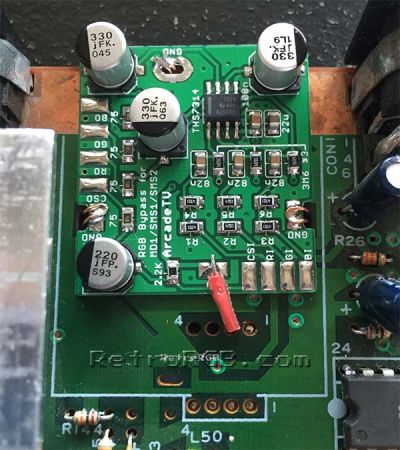
- Position the board where the RF modulator used to sit as shown below. You'll then want to run thick wire through the three ground holes, then bend and solder them on each end. Also, connect a small wire to the 5V hole on the RF adapter's mounting hole. Double check with a multimeter that it's the correct 5V location:


Tapping RGBS from the VDP
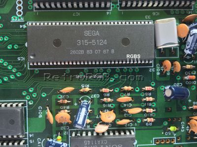
- Locate the Sega 315-5124 chip on your board. Tin the red, green, blue and composite sync pins (26, 27, 28 & 29, respectively), as well as the inputs on the bypass board and connect the two.
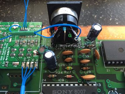
- Connect the RGB to the multi-out. It may be preferable to solder to the top of the multi-out to keep the wires from getting pinched. The picture below shows the bypass board with the capacitors removed (for use with stock SMS cables) and RGB-out coming directly from the chip (the B&G wires aren't connected, as they would have blocked the view in the picture).
- Please note that if you're using a different output connector, you'll also need to connect ground and possibly 5V.
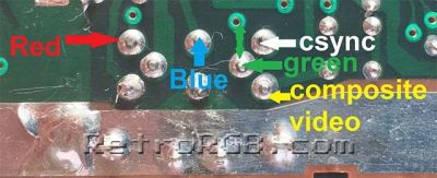
- Alternatively, you can solder directly to the pins on the bottom of the DIN connector. (composite video pin is just shown for reference):
- Please note that if you're using a different output connector, you'll also need to connect ground and possibly 5V.


French Consoles
All French Master System consoles, including the Master System II, only have RGB output, but it is neither amplified or buffered, and so these systems require the use of a special RGB cable. Performing an RGB bypass on these is fairly easy since they lack a video encoder and wire up the RGB output directly from the VDP using either bodge wires or jumper links.
- On the French model 1, there will be three bodge wires connecting the RGB signals from the VDP to where the output pins on the video encoder would be. Desolder these wires from the video encoder vias and make note of what wire belongs to what signal. They can be denoted based on the resistor footprint at the other end of the wire:
- R6: Red
- R7: Green
- R8: Blue
- Composite sync can be taken from where R19 connects to the DIN connector.
- Place the bypass board where the RF modulator would normally sit, as per the "Removing the RF Modulator" procedure above.
- Connect the existing bodge wires to the RGB input pads on the bypass board, then connect the output wires from the bypass to the vias for the video encoder output pins.
For the French SMS II, the procedure is similar but involves removing jumper links instead of wires.
- Desolder the jumper links for red, green and blue. They are labeled on the board as "JPR", "JPG" and "JPB" respectively.
- Place the bypass board where the RF modulator would normally sit, as per the "Removing the RF Modulator" procedure above.
- Solder wires from the rightmost vias on JPB and JPG and the front-facing via of JPR to the blue, green and red input pads of the bypass board.
- Solder wires from the leftmost vias on JPB and JPG and the rear-facing via of JPR to the blue, green and red output pads of the bypass board.
Troubleshooting
- If the screen is too dark, your RGB cable most likely has 75 ohm resistors in the console side of the cable. If that's the case, simply remove the resistors on the bypass board and bridge the connections (as shown in the above picture).
- There will always be some noise or jailbars on SMS consoles, but after performing the mod, it should be greatly improved.