Genesis talk:Triple Bypass Mod: Difference between revisions
No edit summary |
mNo edit summary |
||
| Line 14: | Line 14: | ||
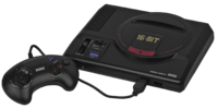
| rowspan=10 align=center | Model 1<br />[[File:Genesis_Model_1.png|200px]] | | rowspan=10 align=center | Model 1<br />[[File:Genesis_Model_1.png|200px]] | ||
| align=center | <s title="Placeholder - Guide not created yet!" class="visible"> [[Genesis:Triple_Bypass_Mod_Model_1_VA0|"VA0"]] </s> | | align=center | <s title="Placeholder - Guide not created yet!" class="visible"> [[Genesis:Triple_Bypass_Mod_Model_1_VA0|"VA0"]] </s> | ||
| rowspan="20" | | | rowspan="20" |[[Genesis:RGB_Bypass_Color_Fix|Guide]] | ||
| rowspan="3" |[[Genesis:Preamp_Fix_(Model_1)|Guide]] | | rowspan="3" |[[Genesis:Preamp_Fix_(Model_1)|Guide]] | ||
|- | |- | ||
| Line 77: | Line 77: | ||
|} | |} | ||
</div> | </div> | ||
== Model 1 Audio Fix == | == Model 1 Audio Fix == | ||
Revision as of 01:33, 3 April 2023
The "Triple Bypass" mod is a board that bypasses the audio circuit, video circuit, and optionally, the Model 1 DIN of the Sega Genesis / Mega Drive. It was originally designed by db Electronics, but has become a true open source project with many amazing contributors. There are also versions for the Master System, Nomad, and others being made by members of the community. The latest version's source files can be found on Tianfeng's GitHub (or Zaxour's improved remix) or it can be purchased from Insurrection Industries or RetroGamerStuff.
| This should be considered an expert-only mod and will (in most cases) disable composite video output. |
Guides for Specific Revisions
For all versions of the Genesis 2 except the VA4, a bottom-install is recommended.
| Model | Motherboard Revision | Post-Bypass Color Fix | Audio Fix |
|---|---|---|---|
Model 1
|
Guide | Guide | |
Model 2
|
VA0 | ||
Model 3
|
VA1 | ||
| VA2 | |||
Sega CDX
|
CDX |
Model 1 Audio Fix
If you have a Model 1 Genesis with a VA2 or earlier motherboard, you may want to do this audio fix to remove issues with audio clipping.
Details
Video
The Triple Bypass incorporates a THS7374 video amplifier for the RGB video bypass, pushing the Genesis one step closer to clean video output. Depending on your model, you may need to lift the RGBS pins from the board, or add extra filtering capacitors to the board. If you lift the pins, you'll need to re-create the pullup circuit as documented here.
The Triple Bypass outputs 75 ohm (not TTL) csync on the composite video (cvbs) pin of the multi-out, but not actual composite video. That means unless you use some alternate installation methods (and risk adding interference back into the signal), you can't use composite video cables, but you can use anything that syncs on composite video (including HD Retrovision cables).
If you decide to follow a method that requires lifting the RGB pins of a chip with a regular Triple Bypass Board (Zaxour's excluded), you may want to check out this post by Tianfeng which details an issue with color and its simple fix.
Audio
One of the most exciting features of this board is its integrated Mega Amp 2.0, originally designed by Ace, but then tweaked by MD Fourier software to get levels that match the best version of the model 1. This means anyone installing the Triple Bypass in a have audio output that's equal to, or better than original!
The biggest difference can be heard in Genesis model 2 and 3's though. Genesis 3's will now have excellent quality stereo audio and the model 2's all sound excellent, regardless of motherboard version.
General Description of Signals
Outputs
These pins should (in a standard install) be connected only to the output connector, with no other drivers or loads on them. Note these bullet points if using an existing connector on the board:
- Red, green and blue output pins must not be left connected to the video encoder. All consoles have these pins on the AV port directly connected to the encoder and nothing else. This connection can be broken by lifting pins 21, 22 and 23 on the video encoder (pinout is the same for all revisions) or by cutting the traces connecting them to the port.
- Nothing on the mainboard should be loading the 3BP's driver for the composite pin (labeled '75' on the board). This is frequently omitted from existing guides. There is usually an AC coupling cap and an EMI filter or ferrite bead in series with this pin that can be removed to separate it from the encoder (and, on model 1, the RF modulator). On later versions without an RF modulator you could also lift pin 20 of the encoder.
- The two stereo audio pins should not be driven by the existing circuitry on the main board. This is usually achieved by removing the output coupling capacitors as indicated in the Mega Amp install guides.
- The 3BP v2 does not drive the mono audio pin (which is unlabeled) on its output, so no conflicts will be caused here. Typically this pin is not used by most cables that connect to the 9-pin Mini-DIN--the major exception is the model 2/3 RF modulator (which won't work without composite anyway). If you are using the model 1 8-pin DIN for your output and you want to provide mono audio, you should disconnect it from the encoder output in a similar manner to the composite pin.
Pass-throughs
These are all signals/nets that are directly connected through, with no difference between the "input" and "output" pads.
- Composite sync is used as an input only by the circuitry on the 3BP v2. The two CSYNC pads labeled "S" on the board are directly connected together, and the board will pass the signal through unaltered if needed. On an install using the existing output port, typically only one of these need be connected. Many existing guides have you cut the CSYNC trace somewhere and jump a wire to the S pad--this is completely unnecessary. On a model 2 bottom install, you need not do anything besides solder to the DIN pins and this signal will be connected correctly.
- Note that the 3BPv2 board provides an extra pull-up resistor for CSYNC! This is R1 on the 3BPv2. Ensure that only one pull-up resistor is connected to CSYNC! You can achieve this by either removing R1 from the 3BP, or removing the stock pull-up from the mainboard if it's still in circuit
- Ground is typically connected to the mainboard via the mini-DIN port itself. A ground pad is provided just in case, but usually need not be used. The three large through-hole pads on the mini-DIN footprint are all connected to ground.
- 5 volt power is typically present on the mini-DIN ports of model 2 and 3. However, in contrast to the other two nets in this list, it can sometimes be beneficial to re-route it (by disconnecting the existing feed to the mini-DIN and running a wire directly from the 3BPv2 to the voltage regulator).
Inputs
These are inputs to the Triple Bypass board's amplifier circuits, and have some specific requirements for how they're wired up.
- Red, green and blue inputs of the 3BP should be connected with low impedance to the corresponding output pins of the VDP (or ASIC, or GOAC).
- For the best picture quality, each of these signals should be connected by one 5.6 kiloohm resistor to 5 Volt. Current versions of the 3BP v2 board do not have these resistors, so they must be provided externally. These resistors are already present on the mainboard and the existing ones can be used, but see below.
- In the stock circuit, these signals are connected to the encoder network via a voltage divider and AC coupling capacitor. All of this should be disconnected or else the signal will be darker than intended. Usually, removing the 4.7k series resistor from each is all that is required.
- On some revisions, it may be desirable to lift the RGB pins of the VDP (or ASIC, or GOAC) and connect them directly to the 3BP. If this is done, the 5.6k resistors to 5V should be added somewhere.
- XL/XR and CL/CR inputs are very electrically similar so some points apply to both.
- XL and XR connect to pins B01 and B03 of the cartridge slot. These audio inputs are fed by add-ons like the 32X or flashcarts like the Mega Everdrive Pro or MegaSD.
- CL and CR connect to pins B29 and A29 of the expansion slot. These audio inputs are fed by the Sega CD/Mega CD when the mixing jack is not being used.
- For all four of these signals, there are usually more convenient locations on the mainboard to connect them than directly to the slots, as indicated in the Mega Amp guides. These nets are fairly low impedance and not particularly vulnerable to noise.
- All four of these signals need one 75 ohm load/biasing resistor to ground. The jumpers on the 3BPv2 can connect its built-in 75 ohm resistors if there are none already in circuit.
- These signals should be disconnected from the existing audio circuit, usually by removing capacitors.
- YL/YR are the FM audio inputs and should be connected to the MOL and MOR pins of the FM DAC on the board. This is either a YM2612, ASIC or GOAC.
- If your board has a discrete YM2612, there should be 2.2k resistors to ground on each of these signals--typically these are already present.
- Nothing else should be connected to these pins. (Removing capacitors is typically enough).
- PSG is the monaural signal from the integrated PSG/DCSG.
- Your console should have only one of the following chips. Whichever one is present has this signal on the pin labeled "PSG" (though there are other places to tap it):
- Original VDP (pre-VA7 model 1): 315-5313
- First integrated ASIC (VA7 model 1, multiple model 2 revisions, Nomad): 315-5487, 315-5660, 315-5700, 315-5708 and variants (-00, -01 etc).
- Toshiba ASIC (VA2 and VA2.3 model 2): 315-5685, 315-5786
- First iteration GOAC (VA4 model 2, VA1 Genesis 3): 315-5960
- Second iteration GOAC (VA2 Genesis 3): 315-6123
- This signal always needs a pull-down/load/biasing resistor to ground. On most revisions, this is 2.2 kiloohm, while on Toshiba ASIC revisions (Model 2 VA2 and VA2.3) it is recommended to use 750 ohm. The 3BP v2 offers both of these options via the "d" jumper.
- Your console likely already has a pull-down resistor present on its main board--however, it may not be the correct value. Any wrong value pull-up resistors should be removed, as well as any other loads on the signal (capacitors or connections to existing audio circuitry).
- If the correct value of pull-up resistor is present, don't add a redundant one by soldering the "d" jumper. This is a mistake often made on early model 2 boards, as the instructions assume you removed the pull-down on the mainboard but many people miss it.
- Your console should have only one of the following chips. Whichever one is present has this signal on the pin labeled "PSG" (though there are other places to tap it):