3DS:2DS USB-C Charging Port Mod: Difference between revisions
Jump to navigation
Jump to search
(Created page with "thumb|2DS USB-C mod thumb|2DS USB-C Kit This tutorial goes over how to add a USB-C breakout board to a 2DS, allowing the battery to be charged over USB-C. This mod replaces the original power port. ==Requirements== The following materials are required for this mod: * [https://www.etsy.com/listing/1459640624/nintendo-2ds-usb-c-replacement-charge USB-C board]. Other boards will work, but this one specifically i...") |
No edit summary |
||
| Line 6: | Line 6: | ||
The following materials are required for this mod: | The following materials are required for this mod: | ||
* [https://www.etsy.com/listing/1459640624/nintendo-2ds-usb-c-replacement-charge USB-C board]. Other boards will work, but this one specifically is safe to use with USB-C to USB-C cables as well as USB-A to USB-C cables. | * [https://www.etsy.com/listing/1459640624/nintendo-2ds-usb-c-replacement-charge USB-C board]. Other boards — such as [https://github.com/giltesa/Nintendo-2DS-USB-C-Kit this open source board] — will work, but this one specifically is safe to use with USB-C to USB-C cables as well as USB-A to USB-C cables. | ||
* Soldering iron, solder, and flux | * Soldering iron, solder, and flux | ||
* A drill and drill bits OR small grinding pen | * A drill and drill bits OR small grinding pen | ||
Latest revision as of 23:26, 9 November 2023
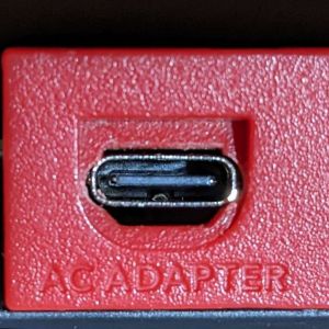
This tutorial goes over how to add a USB-C breakout board to a 2DS, allowing the battery to be charged over USB-C. This mod replaces the original power port.
Requirements
The following materials are required for this mod:
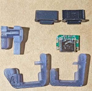
- USB-C board. Other boards — such as this open source board — will work, but this one specifically is safe to use with USB-C to USB-C cables as well as USB-A to USB-C cables.
- Soldering iron, solder, and flux
- A drill and drill bits OR small grinding pen
- A file to file plastic (optional)
- A hot air station and kapton tape OR ChipQuik for removing the original port
Replacing the Port
- Disassemble your 2DS and remove the motherboard from the shell, as well as the top plastic bar that contains the power port hole.
- Add flux to the original charging port and add solder to the existing pins.
- Use ChipQuik or a hot air station to remove the charging port.
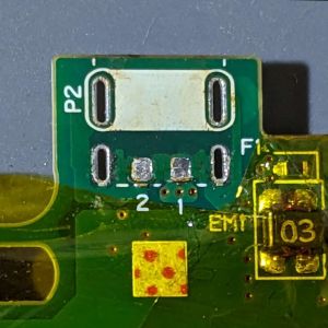
- Remove the solder from the pads on the motherboard and then apply solder to each of the four slot-shaped pads and the pad marked "1". Add just barely enough solder that the solder is domed, equal in height, and not flat.
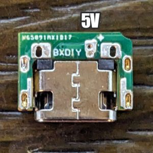
- Add solder to the pads on the underside of the USB-C PCB to fill the holes, including the pad marked 5V in the image below. Ensure the solder lies flat.
- Identify your motherboard version. If the power port area looks like the above with the "P2" marking, it is a type A motherboard.
- Slide the USB-C PCB down into the resin jig marked with the letter matching your motherboard type.
- Apply some flux to the pads on the bottom of the USB-C PCB and on the motherboard.
- Look at the jig and note that there is a slot cut through it. Slide the jig with the USB-C PCB onto the motherboard. You may need to lift the PCB to slide it all the way in.
- Press down on the PCB to lay it on top of the motherboard. It will not sit completely flat.
- Using a cloth or similar, cover the top side of the PCB so that you can lightly apply pressure to keep the USB-C PCB against the motherboard.
- Attach the PCB to the motherboard:
- If using a hot air station, heat the bottom of the motherboard while continuing to apply pressure until the PCB flies flat on the motherboard.
- If using a soldering iron, heat each of the four slotted pads on the bottom of the motherboard as well as any of the three vias near the 5V pad. You will need to heat point over over and over in the same order until each one is molten and the PCB lies flat on the motherboard.
- Use a multimeter to check:
- That the 5V pad has continuity with the pad of F1 closest to the USB-C port.
- That the metal shield of the USB-C has continuity with a GND point on the motherboard, such as the SD card slot.
- That the 5V pad does not have continuity with GND.
- Gently slide the jig off of the PCB. Keep in mind that the PCB connection to the motherboard is only as strong as your solder, so you should avoid putting any pressure on it.
Cutting the Port Hole
- Insert the longer half of the larger half of the drill jig into the plastic hoop and porter port hole.
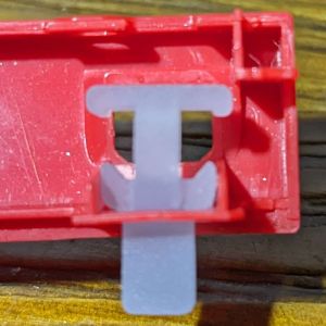
- Insert the other half of the drill jig into the power port hole and press the halves of the jig together.
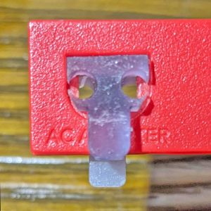
- Use a grinding pen or select the largest drill bit that can fit inside of the holes in the drill jig. Carefully drill both holes. You may want to sand or file it smooth.
- Gently place one of the two black USB-C port covers onto the USB-C port. This serves to hide the gap between the USB-C port and the plastic of the 2DS shell. Do not force it on.
- Put the motherboard back into the bottom shell. Plug in a USB-C cable and verify that the power LED comes on. If it does, you can reassemble the 2DS.
