Jaguar:50/60hz Switch: Difference between revisions
(Edited the introduction to mention the jumper for the video encoder and the clock crystal being different between PAL and NTSC motherboards, added info about changing the video encoder color ouput to NTSC(443)a nd made a templete for replacing clock cryst) |
(Added photo to show where to install the jumper on R19 for NTSC color output.) |
||
| Line 14: | Line 14: | ||
== Setting the video encoder to NTSC color == | == Setting the video encoder to NTSC color == | ||
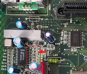
On the top side of the motherboard near the cartridge slot, locate the pad next to the video encoder. It may be marked as "R19". Place a [insert correct SMD resistor size here] 0 Ohm resistor on the pads and solder it in place. The system now outputs NTSC, though if the colock crsytal Y1 wasn't replaced, it may output NTSC4.43 (NTSC color with 4.43 MHz color carrier frequency) instead of PAL60. | [[File:JaguarPALNTSC-video-encoder-jumper.jpg|thumb]] | ||
On the top side of the motherboard near the cartridge slot, locate the pad next to the video encoder. It may be marked as "R19". Place a [insert correct SMD resistor size here] 0 Ohm resistor on the pads and solder it in place. The system now outputs NTSC, though if the colock crsytal Y1 wasn't replaced, it may output NTSC4.43 (NTSC color with 4.43 MHz color carrier frequency) instead of PAL60. | |||
== Replacing clock crystal Y1 == | == Replacing clock crystal Y1 == | ||
TODO: Write all this and find a modern compatible clock crystal. | TODO: Write all this and find a modern compatible clock crystal. | ||
Revision as of 22:29, 14 February 2024
The NTSC and PAL motherboards for Atari Jaguars are nearly identical, except for a different clock crystal and two jumpers that are set differently on PAL motherboards. When a 0 Ohm resistor is in place on R140, the system to run at 50Hz instead of 60Hz. Whereas a 0 Ohm resistor not being in place on R19, makes the video encoder output PAL over RF, Composite and S-Video. In addition to that, the clock crystal Y1 was changed from a 14.3MHz crystal to a 17.7 MHz crystal for PAL's 4.43MHz color carrier frequency.
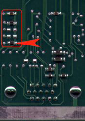
Removing Jumper R140
On the bottom side of the motherboard near controller port 2, locate the resistor. It may be marked as "R140". Heat each side and add fresh solder and remove the resistor. You may want to keep the resistor attached on one pad so you can always undo the mod.
Alternatively, you can install a SPST switch and solder a wire between each leg and the pads so that you can switch between 50Hz and 60Hz.
Setting the video encoder to NTSC color
On the top side of the motherboard near the cartridge slot, locate the pad next to the video encoder. It may be marked as "R19". Place a [insert correct SMD resistor size here] 0 Ohm resistor on the pads and solder it in place. The system now outputs NTSC, though if the colock crsytal Y1 wasn't replaced, it may output NTSC4.43 (NTSC color with 4.43 MHz color carrier frequency) instead of PAL60.
Replacing clock crystal Y1
TODO: Write all this and find a modern compatible clock crystal.

