Dreamcast:Rechargeable VMU Battery Mod: Difference between revisions
Jump to navigation
Jump to search
Lexlocatelli (talk | contribs) No edit summary |
m (Derf moved page Dreamcast:Rechargeable VMU Battery Mod to Dreamcast:Rechargeable VMU Battery Mod) |
(No difference)
| |
Revision as of 13:30, 9 June 2023
The Dreamcast VMU requires 2 CR2032 batteries in order to function outside of the Dreamcast controller. The VMU also constantly drains the batteries, even in sleep mode. It even drains the batteries when in a powered-on controller. These batteries are starting to get more expensive, and can get pricey if you have multiple VMUs that you would like powered at all times. Instead of using CR2032 batteries, we can add a rechargeable Lipo battery, along with the circuitry required to charge the battery while plugged into a controller!
Video Guide: https://youtu.be/iextCUs2V5w
Required Materials
- Basic soldering tools (Iron, solder, solder wick)
- 24GA or 26GA wire
- Wire strippers of an appropriate size
- Size 1 Phillips Head Screwdriver
- A TP4056 charging board, in MicroUSB form. There are also USB-C versions, which are harder to work with.
- A Lipo battery. This should be one of the following sizes: 302030, 242530, or 202030.
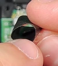
- Non-conductive tape, such as electrical tape or kapton tape.
- Flush cutters and optionally a rotary tool for modifying the VMU shell
Preparing the VMU
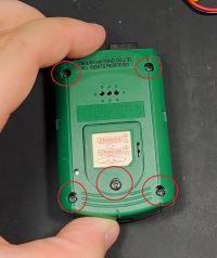
- Disassemble the VMU by removing the battery cover and 4 screws on the back of the shell. (Click the example pictures to enlarge them.)
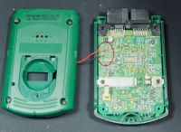
- Desolder the positive and negative speaker wires so you can separate the shells.
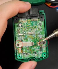
- Remove the two screws holding the positive (shorter) and negative (longer) battery posts.
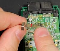
- Cut the negative battery post somewhere behind the bend in the metal.
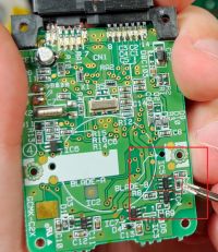
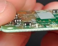
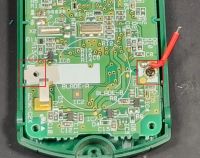
- Now that the two screws are gone, pull the motherboard from the shell. Desolder components R5 and IC5, shown below.
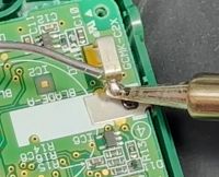
- Bridge the two pads from component R5, either using a small wire or a large blob of solder.
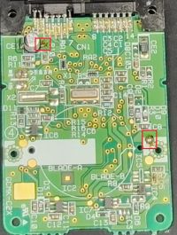
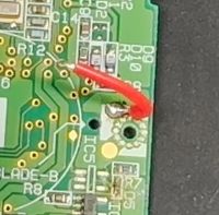
- Tin one of the pads on the positive battery post, and tin EITHER Pin 2 on the VMU connector, or the positive side of the capacitor shown below.
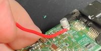
- Solder a short (2-3cm) piece of wire to the positive battery post you tinned earlier, as you won't be able to access it once the battery is in place.
- Solder a longer (4-6cm) piece of wire to Pin 2 or the positive side of the capacitor, whichever one you tinned earlier.
- Replace the screws from the battery posts. Do NOT put the positive battery post back, JUST the screw. DO place your newly trimmed negative battery post before screwing down.
- Add a blob of solder to the vertical side of the negative battery post.
- Create two different double sided pieces of electrical tape, keeping it as thin as possible. One is for the battery, one is for the charging board.
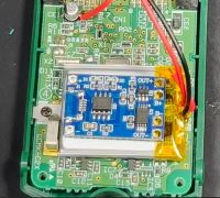
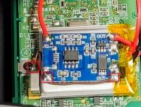
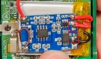
- Add the battery to the motherboard with the double sided tape, with the wires facing right side of the VMU. Then place the charging board on top, with the Out+/B+/B-/Out- side facing the right side as well (same side as the battery connector).
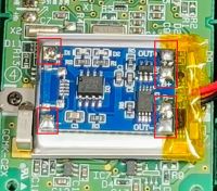
- Add solder to all 6 pads on the charging board (Out+/B+/B-/Out-/In+/In-)
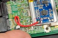
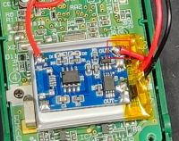
- Connect the wire from Pin 2/Capacitor positive to In+ on the charging board
- Connect the short wire from the VMU's positive battery pad to the Out+ pad on the charging board
- Connect a wire from Out- to the large blob of solder on the negative battery post, and connect a wire from In- to the large blob of solder on the negative battery post.
- Connect the positive and negative wires from the battery to the charging board's B+ and B- pads, being very careful not to let them touch.
Modifying the VMU shell
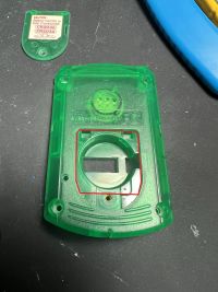
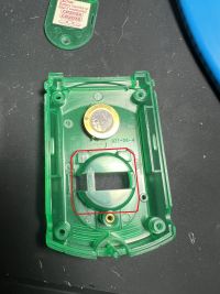
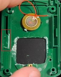
- Now you must cut the VMU's back shell in order to fit the battery and BMS board. Cut away the section highlighted below, getting as close to the screw post as possible without removing it. You'll also need to shave down the plastic that faces into the case as much as possible, testing your fit and cutting more as needed.
- Here is an example shell, cut down with a dremel, tidied up with flush cuts, and finished with a craft knife to shave down as much as possible.
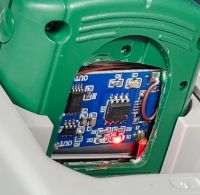
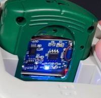
- Now, place the shell back on, while leaving the battery cover off. This will let you see if the board is charging. There will be a red LED while the board charges, and a blue LED once the battery is full.
- Now you're done! The VMU should charge in 5-10 minutes, and will last quite a while. Every time you use the VMU in your controller, it will recharge to full!
