AV:RetroTINK-4K: Difference between revisions
No edit summary |
No edit summary |
||
| Line 1,476: | Line 1,476: | ||
*'''Auto-Crop:''' When set to "On", the RetroTINK-4K will use the DV1 infoframe data to automatically crop any black borders. Auto-Crop can be disabled by choosing "Off". | *'''Auto-Crop:''' When set to "On", the RetroTINK-4K will use the DV1 infoframe data to automatically crop any black borders. Auto-Crop can be disabled by choosing "Off". | ||
Note that DV1 input can automatically trigger profile changes, using the Auto Load DV1 Profile function. | Note that DV1 input can also automatically trigger profile changes, using the [[AV:RetroTINK-4K#Load_Profile|Auto Load DV1 Profile]] function. | ||
===A/DAC=== <!--T:157--> | ===A/DAC=== <!--T:157--> | ||
Revision as of 23:44, 5 July 2024
| This page is a work in progress. It's possible that not all features or settings are covered at this moment, and additions will be made as new features are introduced. This page is intended for documentation and assistance with the RetroTINK-4K. If you are looking for information on using other retro upscalers, please refer to their wikis and documentation. |
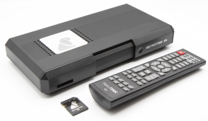
The RetroTINK-4K (commonly abbreviated as "TINK-4K" or "RT4K") is an advanced video scaler from RetroTINK LLC. Building on the functionality of the RetroTINK-2X and RetroTINK-5X, the RetroTINK-4K offers high-end video scaling and processing at resolutions up to 4K60. This page serves as both a RetroTINK-4K instruction manual, as well as a How To Guide to help you understand how best to use each of its functions.
Below is a table mapping out all the pages on Console Mods that cover the RetroTINK-4K:
| Main Page | Firmware Repository | System Specific Settings | SD Card Inventory |
|---|---|---|---|
| The page you're reading right now! Covers all operations of the RT4K, including Additional Guides, Community Resources and FAQ / Troubleshooting. | An external GitHub repository with downloads for every officially released RT4K firmware. | Details the settings you may want to consider when first connecting a console to the RT4K. | Covers the SD Card's contents, such as Profiles, CRT Mask profiles, and CSCs (Color Correction Profiles). |
Overview
The RetroTINK-4K is the latest evolution of the RetroTINK line of video line doublers and upscalers. For schematics including the dimensions and measures of its casing, see the CAD and Schematics archive.
Below is a list of some standout features:
Output
- HDMI® up to 4K60
- Flexible output modes including 480p, 1080p, 1440p at various refresh rates
- Custom modelines on the SD card
- Fully buffered video (drop-free on input changes), Gen Locked and Frame Locked sync modes
- HDR10 output with full color correction to Rec. 2020
- High frame rate output modes: 1440p120, 1080p240
- Optional deep color output (10 bits at 4K60 may not be compatible with all displays)
- Up to 8-ch LPCM audio
Inputs
- Supports for virtually all analog formats:
- HD15/VGA: RGBHV, RGBS, RGsB, YPbPr, S-video and Composite
- SCART: RGBS, RGsB, YPbPr, S-video and Composite
- Rear RCA: RGsB, YPbPr and Composite
- Front Composite
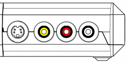
- Front S-Video
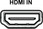
- HDMI® Input supporting up to 1080p60/1200p (CVT-rb) and up to 8 channels LPCM.
- Analog audio input sampled at up to 96kHz/24-bit with full gain control
- Optical TOSLINK audio input supporting 2-Ch LPCM or compressed surround
- HDMI® audio supports up to 8-ch LPCM
Analog Video
- Automatic gain calibration
- Automatic phase calibration
- Automatic input cropping to trim borders
- Full control of gain, offset and sample rate
- Console specific automatic sample rate detection (experimental feature)
- Support for a wide variety of off-spec arcade and PC boards (may require custom profiles to properly trim and center the image)
- Max input resolution of 1920x1080p60 or 1920x1200p60 CVT-rb
- Robust composite/S-video decoder with multi-region support (NTSC, PAL, PAL-60, SECAM)
Scaling
- Fully flexible, custom cropping and zooming in the horizontal and vertical space independent of other settings
- Automatic aspect ratio correction to 4:3 or 16:9
- Motion adaptive deinterlacing including film modes for 3:2 and 2:2 inverse telecine (experimental feature)
- RoTATE 90 deg CW or CCW (for 240p, 288p and 360p inputs)
CRT Simulation
- Multiple CRT beam profiles
- Fully configurable CRT beam strength and intensity modulation
- Adjustable CRT masks and strength
- Interlaced video simulation with offset scanlines
- LCD simulation patterns that automatically adapt to scaling, including non-integer factors
Image Processing
- End to end RGB pipeline with internal 12-bit precision
- Conventional gamma and approximated modes to minimize quantization error
- Advanced and fully configurable gamma and perceptual quantizer (HDR)
- Advanced color gamut transforms to simulate different display technologies
- Black frame insertion engine with customizable pattern and intensity
- Linear light processing
User Interface
- Advanced OSD menu-based system
- SD Card for storing custom modelines, firmware updates and saving profiles
- Support for over 100,000 profiles
- Custom premium remote control
Product Contents
A new RetroTINK-4K package will come with the following items:
- 1x RetroTINK-4K unit
- 1x 8GB SD Card, pre-loaded with software and profiles.
- 1x USB-A / USB-C SD Card Reader
- 1x Remote Control
- 1x USB-A to USB-C Power Cord
| The package does not include an AC adapter or HDMI® Cable. For power, we recommend using a 5V 2A USB-A adaptor, similar to what's packaged with modern phone chargers. We do not recommend plugging the RT4K into the USB ports of your display, as they often do not provide enough power and may result in operation errors. For HDMI®, any HDMI® 2.0 or higher cable rated at 18Gbps or more will work with the RT4K. Please make sure you purchase products from reputable vendors. |
Getting Started
The RetroTINK-4K is designed to be powerful, yet easy to use and quick to set up. Here are some steps to get started using the RetroTINK-4K:
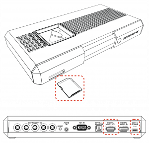
- SD Card - A card is included with every RetroTINK-4K that includes the firmware and profiles. Please make sure this card is inserted in the device, as it is required for proper operation. If you lose the card or have any issues with it, any SD card, or microSD card with adapter, formatted with FAT32 SD may be substituted. Up to 1TB cards have been tested after having been formatted with this tool.
- USB-C Power - Connect a USB-C cable supplying at least 5V/2A to the USB-C power input on the 4K.
- Video Output - Connect an HDMI® cable (2.0 or higher / 18Gbps+) from the RetroTINK-4K output to your display.
- Video Input - Connect your device's output to any of the RetroTINK-4K's inputs. More information on supported connections can be found in the Inputs section.
- Confirm Video Output - By default, the RetroTINK-4K outputs 4K60. If you don't see any picture, confirm that your display supports 4K60, or press the button on the remote that matches the resolution of your display (1080p, 1440p, or 480p). See the Remote and Output sections for more information.
- Select Your Input Source - Press the "Input" button at the top of the remote, then choose the port and signal your game system is using.
- Enjoy - Once your video source is visible, you're ready to go! Enjoy the high quality, low latency scaling of the RetroTINK-4K. Time to play the game!
Basic Analog Calibration
With your game up and running, you may want to consider two more steps if you're using an analog video source (note that HDMI® video sources do not require calibration):
Auto Calibrate the Gain - The RetroTINK-4K has a function to automatically calibrate the gain, which works well so long as there's a patch of pure white somewhere on the screen. Gain should be applied on a per-console basis.
Advanced users may want to use the manual gain controls under Advanced Settings > RGB/Component ADC, in tandem with the 240p Test Suite. | |
|
|
Crop the Picture - Cropping the picture is how the RetroTINK-4K scales images to the edges of a screen and centers them. For best results, use a screen that has no black or dark edges. Crops should be applied on a per-game basis.
You can also manually crop and resize the picture if you wish by going to Advanced Controls > Scaling/Cropping. Head to that section to learn more. |
Tweaks, Filters and Beyond
Of course, there is a lot more you can do with the RetroTINK-4K. Here are some more advanced options to explore:
- Update the Firmware
- Choose an Expert-Crafted Optimal Profile
- CRT and Scanline Effects
- Improve Image Vividness with HDR
- Improve Motion Clarity With Black Frame Insertion
Firmware Updates
For firmware notes and downloads, please see the RetroTINK-4K Firmware GitHub page.
Firmware Installation
The RetroTINK-4K can be updated to any firmware (including older firmware), with new releases adding more new features as they are made.
- Power off your RetroTINK-4K and remove the SD card.
- Insert the SD card used for your RT4K into the SD card slot on your computer. If your computer doesn't have an SD card slot, you can connect it using the provided USB adaptor.
- Download the .zip file of the firmware you want from the RetroTINK firmware website.
- Extract the contents of the .zip file (the ".rbf" and "rt4kup.bin" files) to the SD card's root directory. Be sure to replace the existing "rt4kup.bin" file on the SD card, as this is used to determine which firmware to install.
- If you intend to update via the RT4K's menu, do not delete the old *.rbf firmware file. If you do, you'll be forced to update via the Reset button method (see Step 6 below for how to do this).
- Remove the SD card and insert it into the SD card slot on the RetroTINK-4K.
- There are two methods for initiating the firmware installation. The RT4K installs firmware based on the "rt4kup.bin" file.
- Option 1: Power on the RetroTINK-4K, then go to Advanced Settings > OSD/Firmware. In the Firmware update section, select "Check SD Card" to scan for the firmware file, then confirm that you want to install it.
- Option 2: Hold down the blue Reset button on the back of the RetroTINK-4K, then power it on. The firmware installation will begin automatically.
- If the LED blinks red, an install error has occurred. Check the files on the SD card and try again.
- The RT4K will reboot for about 40 seconds, with the front LED flashing pink and then blue. Once done, it will power on again as normal with a green LED. You're done!
| If you can't power on your RT4K or see the LED blink yellow, you've erased your current .rbf firmware file from your SD card. Please make sure both the .rbf and .bin files are on the root of the SD Card, and use the reset button method noted above. |
All custom profiles, CSC files, banner images, input modes, mask overlays and modelines will be kept, as those are stored on the SD card instead of on the RT4K itself.
Significant New Features
If you've just gotten a RetroTINK-4K, this sections lists the significant features added after launch.
- MiSTer DV1 support for auto-decimating and auto-cropping video output from MiSTer cores.
- SEGA Saturn auto-sampling support.
- Rewrite of the 3:2 and 2:2 telecine deinterlacers for improved stability and response time.
- Auto-Cropping for HDMI® input sources.
- Interlaced scanlines can now be added to progressive sources.
- Fixed various HDMI audio compatibility issues including audio glitches for Atomos recorders and missing HDR infoframes when run through AVRs.
Remote
| RetroTINK-4K Remote Diagram | |||||||||||
|---|---|---|---|---|---|---|---|---|---|---|---|
| Button | Description | IR Code | Button | Description | IR Code | Button | Description | IR Code | |||
| Power | Powers on / off the RT4K | 0xE51AB649 | 11 | Profile 11 | 0xD926B649 | 4K | Switches to 3840x2160p 60Hz | 0xCF30B649 | |||
| INPUT | Input source selection menu | 0xEE11B649 | 12 | Profile 12 | 0xD827B649 | 1080p | Switches to 1920x1080p 60Hz | 0xCE31B649 | |||
| OUT | HDMI® Output menu | 0xDF20B649 | MENU | RetroTINK-4K Main Menu | 0xA35CB649 | 1440p | Switches to 2560x1440p 60Hz | 0xCD32B649 | |||
| SCL | Scaling/Cropping menu | 0xDE21B649 | BACK | Back out to previous menu | 0xBD42B649 | 480p | Switches to 720x480p 60Hz | 0xCC33B649 | |||
| SFX | Processing/Effects menu | 0xDD22B649 | △ | Up | 0xE718B649 | RES1 | Custom Output Resolution 1-4.
See Custom Modelines for further explanation. |
0xCB34B649 | |||
| ADC | HDMI® Receiver menu if HDMI® In is currently displayed
RGB/Component ADC menu if an RGB or Component input is currently displayed SDP Decoder menu if a Composite / S-Video input is currently displayed |
0xDC23B649 | ◁ | Left | 0xA857B649 | RES2 | 0xCA35B649 | ||||
| PROF | Profiles menu | 0xDB24B649 | ENTER | Enter | 0xAC53B649 | RES3 | 0xC936B649 | ||||
| 1 | Profile 1 | 0xF40BB649 | ▷ | Right | 0xB04FB649 | RES4 | 0xC837B649 | ||||
| 2 | Profile 2 | 0xF807B649 | ▽ | Down | 0xEF10B649 | AUX1 | "Vertical Only" Auto Crop | 0xC738B649 | |||
| 3 | Profile 3 | 0xFC03B649 | DIAG | Diagnostic Console screen | 0xD728B649 | AUX2 | "Full Crop to 4 by 3" Auto Crop | 0xC639B649 | |||
| 4 | Profile 4 | 0xF50AB649 | STAT | Status screen | 0xD629B649 | AUX3 | "Full Crop to 16 by 9" Auto Crop | 0xC53AB649 | |||
| 5 | Profile 5 | 0xF906B649 | AUTO-GAIN | Auto Calibrate Gain | 0xD42BB649 | AUX4 | 0xC43BB649 | ||||
| 6 | Profile 6 | 0xFD02B649 | AUTO-PHASE | Auto Calibrate Phase | 0xD22DB649 | AUX5 | 0xC33CB649 | ||||
| 7 | Profile 7 | 0xF609B649 | PLAY/PAUSE | Pause current screen | 0xA956B649 | AUX6 | 0xC23DB649 | ||||
| 8 | Profile 8 | 0xFA05B649 | SAFE | Safe Mode | 0xD12EB649 | AUX7 | 0xC13EB649 | ||||
| 9 | Profile 9 | 0xFE01B649 | SYNC-GEN | Sync Lock - Gen Lock | 0xD32CB649 | AUX8 | 0xC03FB649 | ||||
| 10 | Profile 10 | 0xDA25B649 | SYNC-BUF | Sync Lock - Triple Buffer | 0xD02FB649 | - | |||||
IR Codes provided by CharlieBeatnik.
Raw IR Code 0xE51AB649 (NEC protocol) corresponds to address 0x49, command 0x1A.
Pause Button
The Remote features one function that cannot be accessed anywhere else: the Pause function. Pressing this will pause the on the current frame and mute the audio. This frame will even be remembered if you switch to a different input source and back.
- Perhaps the most useful application of the Pause Button is the Deinterlacer/Film menu. Here you'll be able to adjust the deinterlacing settings and see their effects more easily in a scene in motion, letting you tweak them to your liking more easily.
| There are a few situations where using the Pause function will have undesirable results, such as loading a different profile, using the cropping tools, or engaging 3:2 Inverse Telecine. Other functions, such as Black Frame Insertion, won't be visible at all because they require new video frames in order to work. In these cases, simply unpause to resume normal operation. |
Safe Mode
Safe Mode is an option accessible by pressing the blue Reset button on the back of the unit, or by holding down the "SAFE" button on the remote for two seconds. This causes the following:
- Loads the Default profile.
- Sets the input to HDMI® In.
- Sets the output to 480p at 59.94 Hz.
Safe Mode is intended for use in troubleshooting, as any display that supports HDMI® should be required to support 480p60. It's also handy as a fall-back in case you need to return the RetroTINK-4K to a default state for any reason.
LED Light
The RetroTINK-4K has a front LED light that changes color and behavior to convey information about its operation to the user. Below is a chart for LED light behavior and what they mean.
| Color | Description |
|---|---|
| No Light | The RT4K has no power. No electrons, no business. |
| Slow Red Pulse | The RT4K is sleeping, and must be turned on for use. |
| White | The RT4K is booting up, but is not yet ready for use. |
| Green | The RT4K is on and ready for operation. |
| Yellow Flash | System files not found on SD card during boot. Check to see if the SD card is correctly inserted, that it has the .rbf system file, and that the rt4kup.bin file matches it. |
| Purple-Purple Flash | The RT4K is updating the firmware. |
| Blue-Blue Flash | Firmware update is successful. |
| Red Flash | Firmware update error. Check the files on the SD card and try again (the unit is NOT bricked). |
Inputs
The RetroTINK-4K features inputs for a wide variety of signals and connector types, which can be selected in the Input Selection menu. These options can be accessed by pressing the Input button at the top of the remote, or by pressing the Menu button and choosing "Input Selection".
HDMI®
| The RetroTINK-4K supports many resolutions digitally, up to 1920x1080p60 or 1920x1200p60 CVT-rb. Unlike standard consumer equipment, the RetroTINK-4K can tolerate and adapt to arbitrary and off-spec resolutions.
It does NOT support higher resolution inputs, including 1440p and 4K input. If these inputs are fed into the RT4K, it will not display anything. |
Front
The RetroTINK-4K offers S-Video (over Mini-DIN) and Composite (over RCA) inputs in the front (which can be concealed / revealed by moving the sliding panel). The red and white RCA jacks are stereo audio inputs. Red/White front audio inputs are active when either the Front Composite or S-Video input is selected (assuming audio input override is not used).
Rear RCA
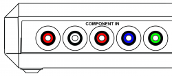
The rear RCA jacks support YPbPr (Component), RGsB, and CVBS (aka Composite) inputs.
| Rear RCA Input | ||
|---|---|---|
| YPbPr | The Rear RCA input supports YPbPr (Component video). The maximum resolution supported is 1920x1080p at 60fps, or 148.5Mhz.
| |
| RGsB | The Rear RCA input also supports RGsB (aka RGB Sync on Green), a flavor of RGB that sends the sync alongside the Green signal. The maximum resolution supported is 1920x1080p 60fps, or 148.5Mhz
| |
| CVBS on Green | Composite video (CVBS) can be used with the Rear RCA inputs. The maximum supported resolution is 480i.
| |
SCART
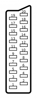
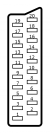
The SCART port is the large rectangular input on the right-hand side of the device. SCART has many different options for video input using the same connector design, as it was designed to carry a wide array of them using a single cable.
| Two M4x0.7 thread screw-holes sit on either side of the SCART port, 70.4mm apart from each other relative to their centers. These allow for a user-made solution to give a more secure fit for the SCART cable (similar to the HD-15 port's screw-holes). |
| SCART Input | ||
|---|---|---|
| RGBS (75 ohm) | RGBS is a form of RGB where sync is sent through a discrete line. The RetroTINK-4K accepts the following RGBS signal formats via SCART: Composite Sync (attenuated), Sync-on-Luma, and Sync-on-composite. They all work by sending information down the Red, Green, Blue, and "Sync" lines. The maximum resolution supported is 1920x1080p 60fps, or 148.5 MHz | |
| RGsB | RGsB sends sync down the green input, using only 3 cables. This RGB format is notably used by the PS2 when in 480p mode via SCART. The maximum resolution supported is 1920x1080p 60fps, or 148.5 MHz | |
| YPbPr | YPbPr is sent through the Green, Blue, and Red pins, respectively. The maximum resolution supported is 1920x1080p 60fps, or 148.5 MHz | |
| CVBS on Pin 20 | Composite video sent through Pin 20, usually through a composite to SCART adapter or if your cable uses sync-on-composite video and you wish to use composite instead of RGB. As with all composite signals, only 240p/480i/288p/576i signals are supported. | |
| CVBS on Green | Composite video can be sent through the Green pin. This would be useful if you use a component (YPbPr) to SCART adapter, just plug composite (yellow) into the Y RCA jack (Green). As with all composite signals, only 240p/480i/288p/576i signals are supported. | |
| Y/C on Pin 20/Red | S-Video (Y/C) can be sent down Pin 20 (sync) and the Red pins. You will need a S-Video to SCART adapter. As with all S-video signals, only 240p/480i/288p/576i signals are supported. | |
| SCART Jack Pinout | |||||||
|---|---|---|---|---|---|---|---|
| Pin # | RGBS (75 Ohm) | RGsB | YPbPr | CVBS on Pin 20 | CVBS on Green | Y/C on Pin 20/Red | |
| 1 | Unused | ||||||
| 2 | Audio In - Right | ||||||
| 3 | Unused | ||||||
| 4 | Ground | ||||||
| 5 | Ground | ||||||
| 6 | Audio In - Left | ||||||
| 7 | Blue | Blue | Pb | ||||
| 8 | Unused | ||||||
| 9 | Ground | ||||||
| 10 | Unused | ||||||
| 11 | Green | Green+Sync | Y | CVBS | |||
| 12 | Unused | ||||||
| 13 | Ground | ||||||
| 14 | Unused | ||||||
| 15 | Red | Red | Pr | Chroma (C) | |||
| 16 | Unused | ||||||
| 17 | Ground | ||||||
| 18 | Ground | ||||||
| 19 | Unused | ||||||
| 20 | Sync | CVBS | Luma (Y) | ||||
HD-15
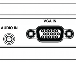
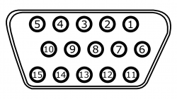
The HD-15 connector (or VGA connector) is commonly associated with PCs, however it's also famously available for the SEGA Dreamcast.
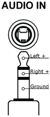
| Unlike SCART, the HD-15 port does not accept audio. When using HD-15, audio should be input using the RT4K's 3.5mm TRS input (associated with the HD-15 port by default), or the TOSLINK "optical" input. |
| HD-15 Input | ||
|---|---|---|
| RGBHV | RGBHV is a form of RGB where information is sent through 5 lines: Red, Green, Blue, Horizontal Sync, and Vertical Sync. The maximum resolution supported is 1920x1080p 60fps, or 148.5 MHz. This is most common for PC sources. | |
| RGBS | RGBS is a form of RGB where sync is sent through a discrete line. The RetroTINK-4K accepts the following RGBS signal formats via HD-15: Composite Sync (attenuated), Sync-on-Luma, and Sync-on-composite. They all work by sending information down the Red, Green, Blue, and "Sync" lines. The maximum resolution supported is 1920x1080p 60fps, or 148.5 MHz | |
| RGsB | RGsB sends sync down the green input, using only 3 cables. This RGB format is notably used by the PS2 when in 480p mode via SCART. The maximum resolution supported is 1920x1080p 60fps, or 148.5 MHz | |
| YPbPr | YPbPr is sent through the Green, Blue, and Red pins, respectively. The maximum resolution supported is 1920x1080p 60fps, or 148.5 MHz | |
| CVBS on Hsync | Composite video sent through the horizontal sync line. As with all composite signals, only 240p/480i/288p/576i signals are supported. | |
| CVBS on Green | Composite video can be sent through the Green line. As with all composite signals, only 240p/480i/288p/576i signals are supported. | |
| Y/C on Green/Red | S-Video (Y/C) can be sent down Green (Y) and the Red (C) pins. As with all S-video signals, only 240p/480i/288p/576i signals are supported. | |
| Y/C on G/R (Enc.) | An enhanced S-Video mode only available on the HD15 connector. (Y/C) can be sent down Green (Y) and the Red (C) pins. As with all S-video signals, only 240p/480i/288p/576i signals are supported. Sampling and Luma calibration is done in the RGB/Comp. ADC Setup menu, and settings noted in the system specific settings apply. | |
| HD-15 Jack Pinout | |||||||||
|---|---|---|---|---|---|---|---|---|---|
| Pin # | RGBHV | RGBS | RGsB | YPbPr | CVBS on Hsync | CVBS on Green | Y/C on Green/Red & Enhanced Y/C | Data | |
| 1 | Red | Red | Red | Pr | Unused | Chroma(C) | Unused | ||
| 2 | Green | Green | Green+Sync | Y | Unused | CVBS | Luma(Y) | Unused | |
| 3 | Blue | Blue | Blue | Pb | Unused | ||||
| 4 | Unused | ||||||||
| 5 | Ground (Horizontal Sync) | Ground (Sync) | Unused | Ground (CVBS) | Unused | ||||
| 6 | Ground (Red) | Ground (Red) | Ground (Red) | Ground (Pr) | Unused | Ground (Chroma/C) | Unused | ||
| 7 | Ground (Green) | Ground (Green) | Ground (Green+Sync) | Ground (Y) | Unused | Ground (CVBS) | Ground (Luma/Y) | Unused | |
| 8 | Ground (Blue) | Ground (Blue) | Ground (Blue) | Ground (Pb) | Unused | ||||
| 9 | Unused | ||||||||
| 10 | Ground (Vertical Sync) | Unused | |||||||
| 11 | Unused | ||||||||
| 12 | Unused | External Transmit (EXT TX) | |||||||
| 13 | Horizontal Sync | Sync | Unused | CVBS | Unused | ||||
| 14 | Vertical Sync | Unused | |||||||
| 15 | Unused | External Receive (EXT RX) | |||||||
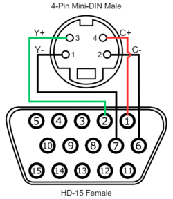
| Enhanced S-Video Wiring | |||
|---|---|---|---|
| Signal | HD-15 (Female) | 4-Pin Mini Din (Male) | |
| Luma (Y) Signal | 2 (Green) | 3 | |
| Luma (Y) Ground | 7 (Green Ground) | 1 | |
| Chroma (C) Signal | 1 (Red) | 4 | |
| Chroma (C) Ground | 6 (Red Ground) | 2 | |
3.5mm TRS Audio
| The RetroTINK-4K allows for audio through a 3.5mm TRS input. This accepts stereo analog audio. By default, this is associated with the HD-15 port, as that port does not accept audio signals. |
Optical Audio
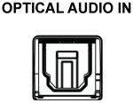
| The RetroTINK-4K offers a discrete optical audio TOSLINK input. This input can accept 2-channel LPCM and compressed surround sound. |
Alternate Audio Inputs
The RetroTINK-4K allows you to reassign audio inputs from their default video source. Go to Advanced Settings, and select "Audio Input" under the "Acquisition" section. The "Input Override" option under "Source" allows the audio for the current input video input to be taken from a different audio source. The only exception is that it is not possible to assign HDMI® audio to a non-HDMI® video source. The reverse, however, is possible.
- This menu also has the Input Swap option, letting you swap the audio input channels (handy for some third-party Saturn cables), or derive mono audio using the left or right channels (useful for single-channel systems like the NES).
| Picture | Name | Description |
|---|---|---|
| RCA (Rear) | The leftmost two RCA inputs in the rear. White and Red, | |
| HD-15 | The 3.5mm TRS input in the rear. | |
| SCART | The SCART input on the side. Audio is fed in through pins 2 and 6. | |
| Front | The red and white RCA inputs in the front of the unit. | |
| S/PDIF | Optical audio fed through a TOSLINK input. |
HDMI® Output
The RetroTINK-4K only outputs via the HDMI® Out port. Note that the RetroTINK-4K can not output video or audio through any other port.
The HDMI® Output menu allows you to set your output resolution, enable black frame insertion, change your colorspace output (colorimetry), and more. Here is a breakdown of the functions in this menu:
Output Resolutions
The following outputs are readily supported by the RetroTINK-4K, and are provided as the first eleven Output Resolution options at the bottom of the HDMI® Output menu. Which resolutions available by pushing their respective button on the remote are also noted. If you are unsure which resolution to use, use the buttons on the remote to quickly try them.
| Resolution | Description | Remote Button? |
|---|---|---|
| 4K60 | Default resolution and framerate for 4k displays, aka 3840x2160p.
Default Resolution for the RT4K |
Yes |
| 4K50 | Intended for PAL games and 24Hz content. | No |
| 1080p60 | Default resolution for 1080p displays. | Yes |
| 1080p50 | Intended for PAL games. and 24Hz content | No |
| 1440p60 | Default resolution and framerate for 1440p monitors, aka 2560x1440p. | Yes |
| 1440p50 | Intended for PAL games and 24Hz content | No |
| 1080p100 | Intended for PAL games and 24Hz content with BFI | No |
| 1440p100 | Intended for PAL games and 24Hz content with BFI | No |
| 1080p120 | Intended for NTSC content with BFI | No |
| 1440p120 | Intended for NTSC content with BFI | No |
| 480p60 | Minimum suggested output resolution for modern displays, aka 720x480p.
Pressing the Reset button on the back of the unit activates this resolution. |
Yes |
| Custom 1 | Custom resolutions loaded from custom[1-4].txt on the SD card.
See Custom Modelines for further explanation |
Yes |
| Custom 2 | Yes | |
| Custom 3 | Yes | |
| Custom 4 | Yes |
| The RetroTINK-4K does not support interlaced output resolutions, such as 480i, 576i, or 1080i. If you require these resolutions, it is currently recommended to try other devices, such as the RetroTINK-5X or the OSSC Pro. |
HDR
HDR is a way for the RetroTINK-4K to output a much more luminous picture for TVs that support it. HDR is intended for use with either Black Frame Insertion or Scanlines and Masks, as it helps compensate for the darkened image.
- Currently, the only option available is "HDR10 [8-bit]".
- You can adjust the brightness of HDR by going to Advanced Settings > Color Correction, then adjusting the "SMPTE 2084 PQ" value. This is useful is you want to play in HDR without scanlines, so that light tones are perceptible instead of being overly bright.
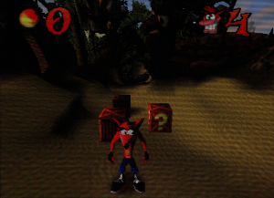
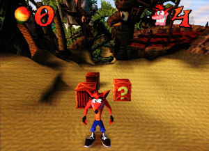
The table below shows two photos of an LG-CX displaying the RT4K using the "PVM 600 TVL" profile, under the HDR CRT Simulation folder. It's impossible to communicate the luminance of HDR in SDR, so here the camera had its exposure set for the HDR photo first, demonstrating the luminance gain compared to the SDR photo.
| PVM 600 TVL scanlines - SDR | PVM 600 TVL scanlines - HDR. |
|---|---|
| HDR is "intended for use with Scanlines, masks, and BFI." If you are not using any of these features, it is best to turn HDR off. If your picture is too dark, consider adjusting your input [adc adjustments], tweaking your output color space with your colorimetry (see below), or making color corrections [CSC Color Correction] |
Colorimetry
HDMI® Output Colorimetry specifies the color space of the HDMI® output. By default, the Auto setting will select Rec. 709, and toggle to Rec. 2100 when HDR is enabled. You may wish to manually set output to Rec. 2020 (without HDR enabled), Adobe RGB or DCI-P3 if your display supports a wider color gamut. This may improve the image quality/accuracy when using the settings in the Color Correction menu.
RGB Range
Set the HDMI® range to Full or Limited, where is it full by default. One setting is not better than the other, but you much make sure your RT4K and display match ranges. If your display uses the limited space, consider turning this option to limited. If your display uses the full range, you may leave the setting alone.
Sync Lock
Sync Lock controls how the RetroTINK-4K synchronizes the output frame rate with the input frame rate, and handles these input changes.
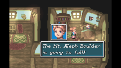
Older video game consoles didn't always have perfect video timings, and while CRTs typically had no problems working with them, these "imprecise" consoles can sometimes have trouble working with modern TVs and capture devices that conform to a more rigid standard. Some games, such as Silent Hill or Chrono Cross on the PlayStation 1, will alternate between 240p or 480i video modes if you are in-game or in the items / pause menu, respectively. On many displays, upscalers and capture devices, this will create a long delay and a "no input detected" screen for several seconds while the device reorients to the new video mode. The issue of a device taking a gameplay-harming amount of time to change between video modes has been colloquially called the "Chrono Cross" problem. How the RT4K handles all of this can be chosen in the Sync Lock section.
- Triple Buffer - Operates the output independently from the input, which results in a stable output signal even if the input signal glitches or changes. However, this comes at the cost of a variable lag, usually between a fraction of a frame to a fraction of a frame plus one whole frame. On occasion, you will see judder when frames need to be dropped or repeated in order to maintain sync.
- Gen Lock - This is the recommended mode as long as your display is compatible with the source's refresh rate. Gen Lock loosely couples the output frame rate with the input frame rate. After a few seconds, the output frame rate will lock with the input frame rate and achieve minimum lag without screen judder. If Gen Lock is giving your equipment trouble, try enabling VRR if they support it.
- Frame Lock - Tightly couples the input and output frame rates. Any change in the input frame rate will cause a disruption in the output signal and a hard re-synchronization.
| Note that the Gen Lock and Frame Lock Sync Lock selections will display "Gen Out of Range!" and "Fr. Out of Range!" respectively when the video input frame rate is too far from the selected output to operate. An input more than 19% faster than the selected output frame rate or 30% slower than the selected output frame rate will trigger this error. When Gen and Frame Lock sync is out of range, the RetroTINK-4K buffer will fall back to the triple buffer Sync Lock method, using the frame rate specified in the selected modeline. |
VRR (Variable Refresh Rate)
The RetroTINK-4K can flag its output as VRR. While the RetroTINK-4K itself never outputs variable frame rates, settings this flag may be useful to force the display to accept a broader range of refresh rates, including if you're using Gen Lock. It is also useful on some displays to prevent re-buffering and other frame rate changes, which will interfere with the RetroTINK-4K's BFI generator. Lastly, some TVs activate a low-lag mode if they detect the VRR flag, which will improve the gameplay experience.
Deep Color
This option changes the bit color depth of the RT4K from 8 bits (Off) to 10-bits (On), increasing the number of colors in the picture. This can be useful if you've used any setting that adjusts the color of the picture. Note that enabling Deep Color will prompt an on-screen confirmation box requiring the user to select "OK" before enabling the feature.
| Engaging Deep Color may cause issues with some equipment like TVs or capture cards, since enabling it while using 4K60 output will exceed the HDMI 2.0 bandwidth spec. In this case, your options are to either disable Deep Color, or use a lower output resolution. PAL systems may have better luck if the 4K50 option is chosen instead, so long as HDR is disabled. |
BFI Control
Gives you quick access to the Strobe and Blur functions of Black Frame Insertion. For explanations on what these do, as well as more BFI controls, head to the Black Frame Insertion (BFI) section.
Audio Output
Surround Sound
The RT4K outputs up to 8 channels LPCM via HDMI®. As of Firmware 1.4.2, and per previous testing all 8 channels are output simultaneously but the channels are correctly routed, so if your receiver reports 7.1 but is only a 5.1 receiver, you should still have correct function from the RT4K.
The RT4K also passes through Dolby Surround® and all previous iterations of Dolby Surround®. This encodes surround sound in stereo signals so it is entirely up to your receiver to decode surround from this signal.
Profiles
| All options should be stored in a single profile. If you load a new profile, consider all previously changed settings lost if you did not save these settings to a new profile. This includes, but is not limited to, inputs, output resolutions, and scanline settings. Consider saving settings for profiles before switching between them for comparison. |
The Profiles section handles all of the profiles provided on the SD card, as well as any you've put there yourself. Profiles allow you to save your settings to load later. This is where you'll find CRT presets, since they're just saved profiles.
- For a list of Profiles provided on the SD card by default, head to the Profiles breakout page.
- For a collection of Profiles made by the community not provided on the SD card by default, head to the Community Profiles section.
Load Profile
- Load From File - Selecting this will bring up a menu where you can navigate through the "profile" folder on the SD card to load up a specific profile.
- Load Default - Loads the Default Profile. The Default Profile can never be deleted or overwritten.
- Auto Load DV1 - Will automatically load a DV1 profile, based on the detected DV1-compatible MiSTer core. Requires the name of the profile to to match the core name, and for the profile to be located in the DV1 folder.
Example: "sdcard/profile/dv1/core-name.rt4".
The arrangement of profiles in the Load From File menu matches the internal file structure of the "profile" folder on the SD card. This means that you can alter the folder structure to your liking if you don't prefer how they're laid out by default.
Save Profile
- Save Current - Overwrites the currently-loaded profile with the current settings. If selected while using the Default Profile, this will work like "Save As New" instead.
- Save As New - Saves the current profile as a new file named "New Profile X", where X is an ascending number. This will be located in the root "profile" folder on the SD card, and can be renamed using a PC.
Assign Profile
This section of the menu allows you to assign one of the twelve number buttons at the top of the remote to a specific profile, using the same SD card navigation menu as the "Load From File" function.
Additionally, this is where you can assign a profile to be loaded up when the RetroTINK-4K is Powered Up. This is not the Default Profile, which can never be changed.
Assigned profiles can be cleared by highlighting the button you want to edit and pushing ◁ (Left) on the remote.
Scaling and Cropping
The Scaling / Crop Setup menu is where you can crop and resize the image. Unlike the RetroTINK-5X, by default the RT4K sizes and positions the image based on the cropping, but this can be overridden with the Scaling Mode setting.
Input Crop
The RetroTINK-4K has robust controls to adjust size, positioning and cropping:
- "Top Trim" and "Bottom Trim" will effectively scale the image up and down in most Scaling Modes.
- To more easily see the edges of the Top and Bottom Trims, set the Scaling Mode to "Auto Fill Integer".
- "Left Trim" and "Right Trim" will adjust the centering of the image, as the RT4K automatically centers the image based on these settings.
- To shift the image left and right, increase the Left or Right trim to push the image in the opposite direction.
Vertical Pre-Scale
The RetroTINK-4K features the ability to "Pre-Scale" video content, or discard scanlines, at a fractional increment of the source input. Discarding vertical lines results in a loss of vertical resolution. This loss can be useful under certain circumstances, such as creating more accurate scanline rendering for 240p visual content output from consoles that run at higher resolutions (such as the Dreamcast or Wii).
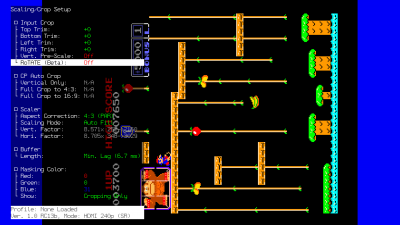
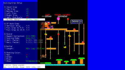
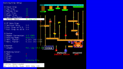
RoTATE
RoTATE (pronounced "roh-tah-tay") is a special feature within the RetroTINK-4K to rotate the image 90 degrees clockwise (right) or counterclockwise (left). This is especially useful for games that may only display their image horizontally, such as many arcade shooters.
| RoTATE Example | ||
|---|---|---|
| Standard Output | 90 Degrees Right | 90 Degrees Left |
The RoTATE mode will only work if the samples per line of your video source is lower than 1024 samples per line (visible in the RGB/Component ADC menu).
- Because the video of Composite and S-Video is locked to 858 samples per line, no additional tweaking is required when using these input sources.
- Further, RoTATE mode will only work with 240p, 288p or 360p resolutions. This is important for titles that mix them with 480i.
If you're using RGB or YPbPr input, visit the RGB/Component ADC section of this page for information on ADC and decimation settings to meet the 1024 samples per line requirement. Similar limits apply when using HDMI® sources: use the Input Decimation settings in the "HDMI® Receiver" menu if the horizontal samples exceed 1024 (for example, MiSTer cores that use pixel repetition).
Auto Crop
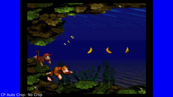
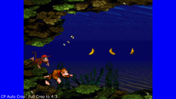
The RetroTINK-4K can automatically crop and set aspect ratio for an input if it is fed a sufficient game screen. This feature works with RGB,Component and HDMI™ sources. Auto Crop looks for the black edges of a game image and crops to them, so use a picture that clearly shows the edges of the video for best results.
| Screens that have any dark edges, as well as letterboxed, pillar-boxed, and window-boxed screens, are not recommended as they will fool the Auto Crop into thinking those are the edges of the image, resulting in an incorrect crop. |
| Name | Remote Button | Effect |
|---|---|---|
| Vertical Only | AUX 1 | Automatically adjusts "Top Trim" and "Bottom Trim" to the top and bottom of the game image. Does not adjust Left Trim or Right Trim, and does not change Aspect Correction. |
| Full Crop to 4:3 | AUX 2 | Automatically adjusts Left, Right, Top, and Bottom Trim to the image, and changes Aspect Correction to "4:3 (PAR)" |
| Full Crop to 16:9 | AUX 3 | Automatically adjusts Left, Right, Top, and Bottom Trim to the image, and changes Aspect Correction to "16:9 (PAR)" |
Scaler
The Scaler section in the RetroTINK-4K is where you'll find the tools that allow you to manipulate the geometry of the image.
Aspect Correction
The Aspect Correction setting chooses the Pixel Aspect Ratio, or "PAR", of the image. This is important because it needs to match the aspect ratio of the display the game is expecting to be seen on, referred to as the Display Aspect Ratio, or "DAR".
The Aspect Correction controls are only available when the current Input (analog or HDMI®) is a resolution with a variable PAR factor, such as 240p, 288p, 480i/p, and 576i/p. Most other resolutions will lock the Aspect Correction setting to their expected PAR, no matter the input. For example, 720p over the PS3's Component cables will lock Aspect Correction to "1:1 (Sq. Pixel)", while 480p over PS3's HDMI® cables will let you choose yourself.
|
The options that are available are:
| Pixel Aspect Ratio | Description | Display Aspect Ratio Use-Case |
|---|---|---|
| 4:3 (PAR) | Uses the common 4:3 Pixel Aspect Ratio, displaying the pixels slightly wider than squares. | Pre-HDMI® video game consoles, which expect to be displayed on the 4:3 DAR of CRT televisions. |
| 16:9 (PAR) | Uses the 16:9 Pixel Aspect Ratio, displaying the pixels even wider than 4:3 (PAR). | Pre-HDMI® games and systems that offer widescreen modes, such as with the PS2 and the Wii. |
| 1:1 (Sq. Pixel) | Uses the 1:1 Pixel Aspect Ratio, displaying the pixels as perfect squares. | Games and consoles that expect a 1:1 PAR but still output a sub-HD signal, such as PSP, and Game Boy games via the Super Game Boy or Game Boy Player. |
If you're using a device that can use more than one Pixel Aspect Ratio, it's important that you set said device to correctly dovetail with the RT4K, so that the game will be shown correctly once it gets to your display.
Scaling Mode
Scaling Mode allows you to select automatic scaling modes or change aspect ratio constraints on manual scaling:
- Auto Fill - Fills the screen based on the selected Aspect Correction aspect ratio.
- Proportional - Allows the Vertical Factor to be adjusted while automatically adjusting the Horizontal Factor to keep the aspect ratio selected in Aspect Correction.
- Free-Form - Untethers the Vertical Factor and Horizontal Factor to allow values outside of the Aspect Correction setting. This setting lets you use the Vert. Factor and Hori. Factor settings to freely transform the image, like on the RetroTINK-5X.
- Auto Fill Integer - Scales the Vertical Factor and Horizontal Factor to the highest possible integer value without exceeding the screen boundaries, while also respecting the ratio selected in Aspect Correction. We highly recommend using the cropping tools to ensure the picture can be as large as possible while using this scaling mode.
Scaling Factors (Transform Tools)
The Horizontal Factor and Vertical Factor settings allow you to stretch and transform the image, either horizontally or vertically. Each factor diplays the multiplier value, the input resolution, and output resolution respectively.
Which of these are available depends on what option the Scaling Mode is set to. Proportional unlocks the Vert. Factor, while Free-Form unlocks both Vert. and Hori. Factors.
The function can be expressed as a simple formula: [Input Resolution] X [Multiplier] = [Output Resolution].
| Horizontal and Vertical Factor Example | |||
|---|---|---|---|
| Axis | Multiplier | Input Res. | Output Res. |
| Vert. Factor | 9.000 | 240 | 2160 |
| Hori. Factor | 2.045 | 1440 | 2945 |
Buffer Length
The RetroTINK-4K allows users to set how much video to buffer before outputting to your screen. The buffer, in conjunction with the Sync Lock mode, are the main determining factors for overall latency.
- Min. Lag - Sets the buffer to only store to bare minimum number of video lines. This option provides the lowest latency.
- 1/2 Frame - Always buffers half a frame.
- 1 Frame - Always buffers a full frame.
Min. Lag is typically compatible, but if you encounter an edge case with screen tearing, try setting this to "1/2 Frame" or "1 Frame".
| Certain movie modes, such as Inverse Telecine, will automatically force the RetroTINK-4K to buffer a full frame. |
Blank Resolution Change
Blank Resolution Change will add a black frame between resolution changes to mask image glitching. This can be helpful to smooth out transitions in games that commonly switch between 480i and 240p. Famous examples include Chrono Cross and Silent Hill on PS1. Blank Resolution change can be set to "On" or "Off".
Masking Color
The masking colour settings allow you to adjust the colour of the mask that displays in the Scaling/Crop menu. By default, the values a 0 Red, 0 Green and 31 Blue. You can also change whether the masking colour is displayed in the cropping menu only, or always (even when the RT4K menu isn't displayed).
Processing and Effects
The Processing / Effects Setup menu is where you can adjust the pixel interpolation, as well as add Scanlines and CRT Masks.
Where are the Scanline Presets?
If you're a regular user of the RetroTINK-5X, you may be surprised to enter this menu and find that there's no Presets available to choose from. This is because they are stored as Profiles on the SD card.
- To load an included CRT Preset, head to the main menu, then go Profiles > Load from File > HDR CRT Simulation, then pick one you want to use.
The "bundling" of CRT Presets as Profiles may seem odd to users of the RetroTINK-5X (where CRT Presets could easily be applied to optimal sampling profiles), however this shouldn't have much impact on the final result. CRT displays are inherently a bit blurry as part of their aesthetic (even PVMs and BVMs), so generic sampling is perfectly acceptable to use for them. If you're using a digital source and decimating it (like Nintendo Switch Online or an HDMI® modded system), you may want to simulate the blur using the Horizontal Interpolation Kernel, and / or the Horizontal Blur function.
The only exception to the above is when you're using the LCD scanlines, as the thin lines dividing each pixel won't appear correctly without scaling the image up by a flat number (such as 4.000x or 5.000x).
RetroTINK-5X Equivalent Scanlines
The following profiles are analogous to similar presets on the RetroTINK-5X, these can be found in the \profile\_CRT Emulation\Basic HDR CRT\ folder on the RT4K SD Card
The profiles on the RT4K use HDR and these screenshots may not appear correctly on your monitor. We strongly encourage you to click on the image and zoom in to see the shape and color of the effects. All screenshots were taken with default settings on both presets and profiles, so you may need to adjust settings to your taste.
| If you liked this preset on the 5x | Then You should try this profile on the RT4K |
|---|---|
Interpolation
Vertical and Horizontal Kernel
Interpolation in relation to video processing is a technique to create more visual information on the output that is given on the input. These processes help make a more visually cohesive image, and reduce effects such as shimmering when the image is scrolling. The RetroTINK-4K offers a handful of interpolation options that can be applied independently across the vertical and horizontal axis.
- Bilinear Sharp - The image is scaled up the maximum integer factor that is within the output size using Nearest Neighbor followed by a bilinear scale to the final output size. This option provides sharp pixels without shimmer at non-integer scaling factors.
- Bilinear Medium - The image is scaled up to the closest integer that is smaller or equal to the output pixels divided by 2 using Nearest Neighbor followed by a bilinear scale to the final output size. This option is somewhat softer than Bilinear Sharp but still sharper than regular Bilinear.
- Bilinear Std - The image is scaled using conventional bilinear filtering.
- Bilinear Soft - This performs linear interpolation over 4 pixels instead of the standard 2 pixels resulting in a very soft image. This may be desirable to produce horizontal blur for CRT effects
- Cubic - Interpolation using the bicubic spline kernel which outputs an image sharper than bilinear but softer than Lanczos.
- Lanczos2 and Lanczos3 - Interpolation using the Lanczos family of scaling algorithms. Lanczos is a popular algorithm that provides good results for natural imagery (i.e. movies) and most 3D games.
- Nearest Neighbor - The image is scaled using Nearest Neighbor for completely sharp pixels, but may shimmer if the Scaling Factors are not set to even multipliers (ie set to non-integer factors).
Anti-Ringing
Anti-Ringing is a toggleable option (On / Off) to reduce the appearance of ringing artefacts when using the Lanczos family of interpolation kernels. By default this setting is set to On, but even then it won't actually be engaged unless you're using Lanczos2 or Lanczos3.
Linear Light
Linear Light is a method of image color and brightness reproduction that may provide more accurate scaling and blending. Linear Light will also alter the appearance of scanline effects, which users may consider an improvement or not based on subjective preferences.
- Linear Light On - The RetroTINK-4K performs inverse gamma mapping at the start of the scaler pipeline and performs all operations in the linear light domain. The output is gamma encoded for SDR modes and PQ encoded for HDR modes.
- Linear Light Off - The RT4K performs all scaler operations in the gamma domain and only performs inverse gamma at the output if needed for color gamut transforms.
Assuming default SDR settings, for linear light to function properly, you have to manually set input factor and output factor to 2.4 in the Color Correction-> Gamma/PQ menu.
Enabling HDR in HDMI® Output->Transmitter, Enabling Color Space Conversion in Color Correction->Color Space Conversion, or Adobe RGB/P3 in HDMI® Output->Colorimetry will adjust Gamma/PQ settings by default to properly allow Linear Light processing.
More information on the benefits of linear light can be found here.
Scanlines
The RetroTINK-4K has customizable scanline generation which can recreate the look of various displays, including early LCD displays. Scanlines are an effect that simulates the appearance of blank scanlines on a display, similar to what you might see on older cathode ray tube (CRT) monitor or television screens. The effect creates generates black spaces between each visible scanline of video, simulating how lower resolution progressive signals would be presented on higher resolution (480i) displays.
Since scanlines are part of the image drawn by a CRTs red, green and blue electron gun, they scale with the image's pixels, and it's for this reason that the RetroTINK-4K's scanlines behave the same. This means that scanlines will appear thinner depending on the resolution of the input source; 240p scanlines are much thicker than scanlines placed on a 1080p input.
- For clarity, on a CRT, every line drawn on the display is a scanline. 240p however only uses half of these, resulting in blank scanlines every second row. This causes the scanlines to be perceptible, hence why these blank lines are called "scanlines" despite not being anything at all.
| Proper simulation of CRT and LCD effects involves many more factors than just the scanline settings, such as but not limited to: Scaling, ADC Sampling, Interpolation / Filter and Color Correction. If this is overwhelming, please try one of the pre-made profiles first (included on the RetroTINK-4K SD card). |
| If your effects don't look correct on your display, your display may not be using 4:4:4 chroma. The methods of enabling this will vary, but solutions include enabling a setting on your TV such as Ultra Deep Color or changing the name and / or icon of the selected input to PC. If no solution is available, setting both the Vert. and Hori. Scaling Factors to even multipliers (such as 4.000x or 5.000x) may help. |
Blank / Black Scanlines
This scanline function determines what formula is used by the scanline generator to translate the replaced video scanline to a "blank / black" scanline.
- Off - Disables the scanline generator. Further settings in the Scanlines section will not have an effect if Off is selected.
- Exponential - A scanline pattern that has the softest profile from bright to dark.
- Gaussian - A scanline pattern similar to Exponential, but with a sharper transition from bright to dark.
- Super Gaussian - A scanline pattern with a very sharp transition from bright to dark.
- Linear - A scanline pattern with a straight ramp from bright to dark.
- Box - A scanline pattern similar to old style emulator scanlines, with no blending from bright to dark. The scanline pattern is either completely on or completely off.
You can adjust the scanlines with the next settings:
- Strength - Adjusts the maximum width of the scanline effect.
- Modulation - Adjust how much the thickness of the scanline effect will change depending on brightness. Specifically, the higher this value, the thicker the black scanlines will be around dark areas of the picture.
- Pseudo Interlace - Draws scanlines with an interlaced order even if the source is progressive. 2x (i.e. 480p → 960i) doubles the resolution so that no vertical detail is lost but results in thinner scanlines. 1x (i.e. 480p → 480i) results in thicker scanlines but loses half the vertical resolution.
If you're inputting an interlaced signal, you should consider going to the Deinterlacer/Film menu and setting the Algorithm to "CRT Simulation". This will cause the scanlines to move up and down every frame, giving a look authentic to how these interlaced signals appear on a real CRT.
LCD Effects
The LCD functions behave differently than the "blank / black" functions, and are instead designed to simulate the appearance of older LCD displays.
- LCD Mono - Will place a 1x1 pixel border around every upscaled pixel in the image.
- LCD RGB - Simulates RGB subpixels per each upscaled pixel (similar to how the CRT masks simulate phosphor artifacts).
With LCD functions selected, the Strength and Modulation options change to "LCD Subpixel Str." and "LCD Vert Str.", respectively, and will retain their values. Despite being available for both LCD functions, they only have any effect on the LCD RGB effect.
- LCD Subpixel Str. - Sets how strong the LCD subpixel masking is. Lower values will more strongly "tint" the subpixels the colour of the upscaled pixel they represent.
- LCD Vertical Str. - Controls the size of the horizontal line under each pixel.
Color Bleed
Color bleed simulates some of the imperfections of how colors were presented on a CRT. These won't do anything unless a scanline generator is enabled; these won't work with the LCD effects.
- Red Bleed: Enabling Red Bleed simulates a common CRT effect where the Red beam is softer and less focused than Blue and Green.
- Red Convergence: Adjusts a vertical offset of the red data within the scanline effect. Can be adjusted from a -10 to 10 offset.
- Blue Convergence: Adjusts a vertical offset of the blue data within the scanline effect. Can be adjusted from a -10 to 10 offset.
Masks
Masks apply effects equivalent to the shadow masks on a CRT (as well as the similar aperture grilles and slot masks). Since these masks were metal plates that spanned the entire surface of a CRTs glass screen, they're independent of the image drawn by the red, green and blue electron guns. For this reason, masks on the RetroTINK-4K behave the same, and so will NOT adhere to the subpixels of the input you've selected.
The RetroTINK-4K accomplishes the mask effect by tiling an image across the entire screen at 1:1 sizing. Because of this, reducing the RT4K's output resolution will increase the size of the masks.
- Enable - Turns masks Off or On.
- Strength - Adjusts the strength of the masks. "+0" is the neutral value, "+10" is the maximum value, while "-10" is equivalent to turning Masks off.
- Load from File - Takes you to the "masks" folder of the SD card
If you want to make your own masks, head for the Custom CRT Masks section of this page.
Horizontal Blur
The Horizontal Blur function approximates the horizontal blurring present in some CRTs, looking rather like the right-to-left smearing on "3CHIP" Super Nintendos.
- Function - Can be set to "Off" or "IIR LPF".
- Cut-Off Freq - Adjusts the strength of the horizontal blur.
If you're wanting to blur the image in a more "traditional" sense, you'll want to use the Interpolation Kernels in the Processing/Effects menu.
Smoothing
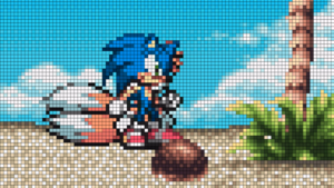
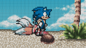
Example 1: No smoothing Wxample 2 yes smoiot
The RetroTINK-4K offers an XBR-style smoothing algorithm to interpolate pixel edges for a smoother look. While intended for 2d-content, it can also help reduce visible aliasing with 3d content.
- Algorithm - Selects between "Off", "XBR Level 1", and "XBR Level 2".
- Noise Threshold - Selects between "Off", "Low", "Medium" and "High" settings.
Color Correction
| Color Correction Example | |
|---|---|
| Before Color Correction | After Color Correction |
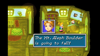
| Golden Sun on Game Boy Advance / GBI Without Color Correction | Golden Sun using csc/Game Boy Interface/Game Boy Advance.txt |
The Color Correction Setup menu controls the advanced color gamut correction and adjustment options on the RetroTINK-4K. The Apply Preset can be used to quickly load Color Correction profiles, such as the ones included on the 1.0 SD Card (more info on 1.0 CSC Profiles here).
Gamma and PQ
The input controls adjust how incoming RGB signals are converted from gamma space to linear light.
- Input Factor: Factor used to convert the input from gamma space to linear light. Input factor is the inverse gamma exponent. Can be adjusted between 0.10 and 5.00.
- Input Lift: Lift adds an offset (raises or lowers black level) to the input gamma conversion. Can be adjusted between -1.00 and 1.00.
- Input Gain: Gain multiplies the output of the input gamma conversion. Can be adjusted between 0.00 and 10.00.
- Output Factor: Available only in SDR, this is the factor used to re-encode the linear ligh output of the video pipeline back to gamma space. Can be adjusted between 0.10 and 5.00.
- SMPTE 2048 PQ: Available only in HDR, where the RT4K uses a perceptual quantizer instead of simple gamma, in order to tonemap the linear light signal into an HDR signal. The control sets the maximum brightness of the PQ in units of nits, which represents the maximum brightness of the tone mapping. Normally this is set to your TVs maximum nit level, however this function can be useful to dim the brightness of an HDR picture. Can be adjusted from 250 to 10,000.
Color Space Conversion
- Apply Preset: Opens the Load CSC Matrix menu, where users can load any saved CSC profiles from the SD card. Most use cases will involve simply applying a preset from the SD card, for example, to apply a color gamut correction to emulate a PVM. The RetroTINK-4K 1.0 SD Card release includes many presets.
You can explore the included CSC presets here.
Information on the Custom Color Matrix preset format can be found here.
- Custom Matrix: Allows the user to turn On or Off CSC by enabling/disabling the Input RGB to XYZ conversion matrix and settings applied to the Gamma/PQ.
- Prevent Clipping: Automatically scale the CSC matrix so that highlights are not lost at the cost of making the image dimmer. Can be set to On or Off.
- Saturation: Controls the color intensity. Lowering it turns the image black and white. Raising it makes the colors more intense. Can be set from -1.0 to +1.0.
Input RGB to XYZ
The user can manually adjust the matrix used to convert the input RGB data into XYZ colorspace. The RT4K automatically chains to correct conversion from XYZ to output RGB depending on the specified output colorimetry (e.g., BT709, BT2020, Adobe RGB, etc.). Each of the conversion functions can be adjusted between -1.75000 to +1.75000.
Advanced Controls
- Transfer Function: Can be set to "sRGB 0.055", "Rec.601/709 0.099", "SMPTE 240M 0.1115" or "Gamma". The various transfer functions linearize the low-end of the gamma curve to avoid bit loss. "Gamma" uses a simple gamma encoding.
- Bit Crush: Lowers the number of colors in the core video signal by reducing the number of bits per color. This is primarily intended for removing rounding errors that can occur in the original signal, e.g. when using GBI, as well as potentially removing noise in some limited cases. Alternatively, it can be used for aesthetic purposes to create a posterization or limited-color mode effect.
- Dithering: Can be set to "On" or "Off". Adds visually imperceptible random noise to the HDMI output to avoid banding and quantization artifacts due to the limit of 8-bit precision.
Black Frame Insertion (BFI)
| BFI is for adding motion clarity. This does not interpolate frames like various settings on modern displays. |
| Please use caution when using BFI. This setting may not be great for people who are sensitive to strobing lights. |
Black Frame Insertion (BFI) is a technique to improve motion clarity with high refresh rate monitors. As an example, a 60fps video source played on a 120hz monitor could have a black frame interstitially placed between every frame. The resulting "image-black-image-black" pattern can increase the perception of motion and fine details. If you have a higher refresh rate monitor, a customizable example can be viewed over at Blur Busters.
The use-case for Black Frame Insertion is to approximate the appearance of a CRT display, which would draw every line left-to-right, with the pixels dimming until they're replaced again for the next frame. Modern displays don't do this and never darken the pixels like this in the drawing process; this gives the effect of "blur" on moving parts of the picture. Black Frame Insertion is a crude but effective method of replicating the feel of looking at a CRT display, and gives the impression of better motion clarity.
BFI cannot be enabled unless the following two requirements are met:
- Set a supported Output Resolution and frame rate - Due to bandwidth constraints, BFI is limited to 1440p or lower resolution output. This also must be a high frame rate: either 100hz or 120hz.
- Set a supported Sync Lock Mode - BFI also cannot be enabled unless you are in Gen or Frame Sync Lock mode.
If both of these requirements are met, the BFI options will be unlocked.
- LCD Saver: LCD display panels may suffer from image retention when using BFI. The LCD Saver helps prevent this by inverting the order of (video frame)-(inserted frame) at the timer value set. LCD Saver can be set to 0, 1, 5, and 10 Minutes. When the frame order is inverted, it may create a momentary glitch in the video output. Note that setting the time value to 0 will display a message screen warning the user of possible LCD panel image retention.
- Min. BFI Limit: Can be set to "On" or "Off". Default "On". Disabling will disable safety limits for BFI strobe effects. Will prompt an additional warning screen when set to "Off".
BFI Control
| Black Frame Insertion (BFI) Settings | ||
|---|---|---|
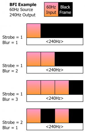
| Strobe: Strobe controls how the output frame rate is divided into the input frame rate. As depicted in the diagram, with Strobe 1, the 60Hz input frame is flashed one time at 240 Hz. At Strobe 2, the 60Hz input frame is flashed twice at 240Hz, with black frames in between. Alternatively, a 60Hz source within a 120Hz output would display for 1/2 of the time 120Hz output window.
Blur: Blur is a duty cycle modifier that works in relation to Strobe to change how many frames the source video is presented in relation to the black frames. In the example diagram (60Hz Source inside a 240Hz output), a Blur of 1 would display the source video 1/4 of the 240Hz window, a Blur of 2 would display the source video 2/4 of the 240Hz window, and a Blur of 3 would display the source video 3/4 of the 240Hz window. Some relationships of Blur and Stobe are locked, such as a 60Hz video source in a 120Hz output window, which would only allow a Blur of 1 (1/2 of the output 120Hz window). | ||
More information about BFI can be found at Blur Busters.
BFI Color
The BFI Color settings allows the user to change how the inserted frame appears.
The Blending Mode setting selects between the following functions:
- Solid: Creates a grayscale inserted frame that can be adjusted with any of the Red, Green or Blue BFI Color settings. A lower BFI Color numerical value is darker, higher is brighter.
- Alpha: In this mode, the inserted frame is a duplicated video frame with a transparent alpha overlay darkening the inserted frame based on the BFI Color setting. A lower BFI Color numerical value is darker/more opaque, a higher value is brighter/less opaque.
- Solid Color: Sets a solid inserted frame with an RGB-assignable color from the BFI Color selections.
- Alpha Color: Inserts a duplicated video frame with an alpha color overlay. The color of the alpha-blended frame is set from the R-G-B BFI Color values.
The Red, Green and Blue BFI Color values allow for customizable colors in the Solid Color and Alpha Color modes, and are an interlocked numerical valued for Solid and Alpha blending modes (R-G-B values cannot be adjusted separately).
Deinterlacer and Film
The Deinterlacer / Film Mode Setup menu allows you to adjust settings for use on interlaced sources, such as deinterlacing methods, apply LCD blending to progressive sources and setup Inverse Telecine.
While tweaking the options under the Mode and Motion Adaptive Settings sections, we suggest using the Pause Button to pause the video on a frame with motion. This will allow you to see the effects of the deinterlacing more easily.
Mode
There are six deinterlacing algorithms to choose from:
- Motion Adaptive - Uses an algorithm to determine whether to use Bob deinterlacing for areas of the screen that change, or Weave deinterlacing for areas that stay the same. Can be further tweaked in the Motion Adaptive Settings section.
- Weave - The current field remains on-screen while the next field is drawn, 'weaving' the two fields together. This is the same as 'disabled' in video players such as VLC, and will result in combing artifacts.
- Bob - Doubles the vertical height of each line to fill the full frame. This causes the image to appear as if it's moving up and down, since the two fields are not aligned in the interlaced signal, but preserves temporal resolution of interlaced video.
- Linear - Linear interpolated Bob (i.e., rather than a pure linedouble, line 2 is the average of lines 1 and 3, line 4 is the average of lines 3 and 5, etc.).
- Blend - The frame is created by averaging lines from the two most recent fields. Produces ghosting.
- CRT Simulation - Similar to Bob, but additionally changes scanline behavior to match that of interlaced content on a real CRT. If Scanlines have not been enabled, this mode will appear identical to Bob. See below for more details on this algorithm.
- LCD Blending - (Progressive sources) Averages the current frame and the previous frame. Produces ghosting that can blend flickering objects. (Interlaced sources) Averages the current field and previous same field, skipping the other field. Eliminates NTSC composite artifacts if the picture is completely still. Not recommended for gaming.
CRT Simulation
The CRT Simulation algorithm is unique enough to warrant its own section. It's used to to simulate the way 480i content is displayed on a real CRT: each frame of a 480i image is actually only 240 lines, and each new frame switches to using lines that were unused in the previous frame. Because of this, CRT Simulation will appear identical to Bob deinterlacing unless you use one of the Scanline functions enabled in the Processing / Effects menu (since they simulate the unused lines), and are viewing interlaced content.
CRT Simulation will also cause your crop settings to be displayed incorrectly, so be prepared to redo your crop after enabling this feature.
| The output frame rate of the RT4K must match the input signal's frame rate in order for the effect to be displayed correctly. This is important if you're using a PAL system, which run at 50 frames per second: if the RT4K is outputting at 60fps (as it usually does by default), the CRT Simulation will not appear correctly for PAL content! |
Motion Adaptive Settings
Motion Adaptive settings apply only to the Motion Adaptive Deinterlacing mode, allowing you to adjust how the Motion Adaptive Deinterlacing operates.
- Sensitivity: Adjusts the sensitivity of Motion Adaptive, between "Min", "Medium", "High" and "Max". The higher this is set, the more weaving will be present for moving parts of the screen, at the benefit of a stabler look for static parts of the screen. Many games will look just fine on the Min. setting, however several games may require Medium or higher. For example, Burnout 3: Takedown on PlayStation 2 has a subtle flickering and noise-like dithering that throws off the Motion Adaptive Deinterlacer for still parts of the screen.
- Noise Threshold: Adjusts how much low-level changes are ignored, so that the deinterlacer doesn't fall back to Bob deinterlacing unnecessarily. Useful for content that has noise and / or dithering present.
- Interpolator:Controls how the Bob function of the deinterlacer is calculated. The bob is either taken from the line above (Upper Field), line below (Lower Field) or the Average of the upper and lower lines.
- Detector: Can be set to "Zero-Lag", which favors the most current field. "Symmetric" favors the previous field, but allows for symmetric motion detection, which may provide cleaner results.
Bob Settings
The only Bob Setting here is the Bob Offset, which adjusts adjusts how far apart each field is from each other. It can be set between "-3" and "+3". This setting is useful for 240p games that were poorly ported to run at 480i, such as Mega Man Anniversary Collection on PlayStation 2.
Film Mode
The settings under Film Mode contain options to help process video content.
Inverse Telecine:
- 3:2 - In this mode, video content that was from a 24 Hz source converted to a 60 Hz signal will play back in a reconstructed 24 fps. This helps applicable video content play with its intended cinematic framerate.
- 2:2 - In this mode, the deinterlacer will rebuild progressive video output from 480i games that run at reliable/stable 30 fps, which effectively converts 480i into 480p. This will result in an increase in visual resolution and clarity. This is especially useful for PlayStation 2 where much of the library is 480i only.
Dejudder 24 Hz: This mode treats telecine material as a virtual 24 Hz source when using Gen Lock and Frame Lock Sync Lock, allowing for true 24 Hz output when combined with a 24 Hz output modeline. It can also be used with a 48, 72 or 120 Hz output modeline. This option only applies when a 3:2 source is successfully detected / deinterlaced.
Cadence Detection
The cadence detection menu offers controls to adjust the RetroTINK-4K's detection of content to pass to the the inverse telecine functions.
- Motion Digital, Motion CP, and Motion SDP: These values change the noise threshold for HDMI inputs, component/RGB inputs and composite/S-video inputs, respectively. Adjusting the noise threshold higher will decrease the detection of false positives, but may miss weaker or nosier telecine signals. Adjusting the threshold lower may increase false readings but allow less stable signals to be processed. Each value can be set from a range of 0 to 500.
- Threshold: Once a signal passes the check of the Motion thresholds, the Threshold number sets how many consecutive detections of a telecine pattern are required before the deinterlacer function activates. This may be helpful for noiser sources such as VHS to further filter out false detections.
HDMI® Receiver
The HDMI® Receiver Setup menu is where you control how the RT4K handles HDMI® In video. This menu is only functional when the HDMI® In port is the currently selected Input. If it is, this menu can be quickly accessed by pressing the ADC button at the top of the remote when HDMI® is selected as the input.
Input Decimation
| Input Decimation | ||
|---|---|---|
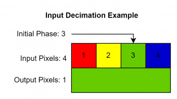
| Input decimation is a function to reduce the horizontal resolution of a given HDMI input. This works by taking the current input horizontal resolution, and reducing it as a division between the Input Pixels and Output Pixels settings. A display of the final output resolution after decimation has occurred is shown in parenthesis at the end of the Input Pixels field.
| ||
Colorspace
Colorspace has options to assign what colorspace the HDMI® input is using, as well as what method to use for 4:2:2 upsampling.
- 4:2:2 Upsampler: Determines how to process digital inputs that are using 4:2:2 chroma subsampling. Can be set to "Linear", which uses a bilinear filter for a smoother appearance, or "Nearest", which uses a nearest neighbor filter for a sharper look (but with more obvious aliasing).
- Input Range: Determines what color range to process the incoming digital signal as. "Auto" should be used unless there is a specific colorspace mismatch. Other settings include "RGB Lim.", "RGB Full", "YCbCr 601", "YCbCr 709", "xvYCC 601", "xvYCC 709", "YCbCr 601 (Full)" or "YCbCR 709 (Full)".
| This setting is independent of the HDMI range in the output menu. This should be consistent with the HDMI range of your console's output (e.g., the Wii U outputs Limited Range, so you set this to Limited Range, but you do not necessarily have to change the HDMI range in the output menu. |
MiSTer DV1
The RetroTINK-4K is compatible with the MiSTer's DirectVideo (aka DV1) video output mode. Compatible cores can output DV1 video over HDMI, which aims to preserve the original content's pixel-accurate video. To work within the HDMI standard, DV1 can often require resolution padding padding (black bars) and pixel multiplication. By including the padding and multiplication info in the HDMI transmission itself (via the HDMI SPD Infoframe), compatible devices can recreate a pixel-accurate image by cropping the frame and decimating any pixel duplication.
- Auto-Decimate: When set to "Infoframe" (recommended when using DV1), the RetroTINK-4K will use the DV1 infoframe data to set the correct decimation factor. "Measure" will try to guess the best decimation setting based on the characteristics of the image. Auto-Decimate can be disabled by selecting "Off".
- Auto-Crop: When set to "On", the RetroTINK-4K will use the DV1 infoframe data to automatically crop any black borders. Auto-Crop can be disabled by choosing "Off".
Note that DV1 input can also automatically trigger profile changes, using the Auto Load DV1 Profile function.
A/DAC
- A/DAC Mode: Allows Analogue consoles that support the Analogue DAC to output an unscaled image to the RT4K. For more information, please visit the Analogue Consoles section of the System Specific Settings page.
- Off: The Analogue console sees the RT4K as a regular HDMI display.
- NTSC: The Analogue console sees the RT4K as an Analogue DAC with the region switch set to NTSC.
- PAL: The Analogue console sees the RT4K as an Analogue DAC with the region switch set to PAL.
| PLEASE NOTE: While using A/DAC mode, the connected Analogue console will output 240p with horizontal variable pixel repetition, in order to allow for cases such as SNES 512-column mode to be rendered correctly. This may cause some scaling settings to not behave how you expect. Nothing is broken, please adjust Input Decimation and Scaling/Cropping until you get the desired image, noting that the initial horizontal scale is 4x what you are probably expecting (2x if you're playing a game that uses 512-column mode), and THIS MAY CHANGE IN THE FUTURE. Additionally, A/DAC Mode when set to PAL will require manual aspect ratio adjustment, and when set to either NTSC or PAL will require significant cropping when used with the Mega Sg due to the Mega Sg's output having a significantly exaggerated overscan area. Due to limitations both with Analogue hardware and with our understanding of the Analogue DAC, none of these issues can be addressed automatically at this time. Finally, please also note that, like with the actual Analogue DAC, changing the A/DAC mode setting while your Analogue console is connected and turned on will result in improper operation from your Analogue console, and is not recommended. |
RGB and Component ADC
The RGB / Component ADC Setup menu is where you control how the RT4K handles analog inputs, such as the RCA, S-Video, HD-15 and SCART ports. This menu is only functional when an RGB or Component input is in use. If that is the case, this menu can be brought up by pressing the ADC button at the top of the remote when YPbPr, RGBS, RGsB, or RGBHV is selected as the input.
Sampling (ADC)
| Sampling (ADC) | ||
|---|---|---|
| ||
Sync (ADC)
- SoG Threshold: Sets the voltage level used to slice the video signal and generate a digital sync pulse. Adjusting this level may help with problematic sources. The voltage can be set between "0.00 mV" and "327.42 mV" in in 11.29 increments.
- Pre-coast: Sets the number of lines before vertical sync to switch from syncing with video source to internally generated sync. Can be set between 1 and 31 lines.
- Post-coast: Sets the number of lines after vertical sync to switch from syncing with video source to internally generated sync. Can be set between 1 and 31 lines.
The coast settings create a padding area away from the vertical sync pulse, so syncing to the horizontal doesn't encounter errors from off-spec signals or glitchy signal transitions. Adjusting Pre-coast and Post-cost values may be helpful when processing off-spec video sources.
- Wide Tolerance: Enables extra sync processing to help with 240p and 288p sources, such as arcade boards or NEOGEO, that may have sync issues due to malformed sync pulses. This should be turned off for normal use as it may cause artifacts for other systems.
Gain
- Pre-ADC: Changes the amount of analog gain applied to the signal before the ADC, functioning as a coarse contrast adjustment. Can be set between -0.7 and +0.8.
- Red,Green, and Blue allows fine adjustment of the individual color channel digital gain, functioning as a finer contrast adjustment per color channel. Can be adjusted between 1.000 and 1.996.
Offset
- Red,Green, and Blue offset provides per color black level / brightness adjustment. Values can be set between -100 and +100.
Auto Calibrate
Auto Phase
Any game screen is sufficient for automatic phasing, but it is recommended to use the 240p Test Suite or other sufficiently patterned screen for eyeballing results. whether you've set automatic sample detection using that menu, or you manually selected Decimation Factor in the ADC page, selecting Auto-Calibrate Phase makes the RetroTINK-4K automatically select the best Decimation Phase and Sub-Phase for your current picture and should give you the sharpest results. It is recommended you run this 3-5 times to make sure the same factors and phases are consistently chosen.
Auto Gain
The Auto Gain function will calibrate the gain levels for the current input, however it only works for RGB and YPbPr sources.
- To use Auto Gain, go to a game screen which has a patch of colour that should be pure white. When you enable the Auto Gain function, the RT4K automatically calibrates the Gain levels based on that white patch.
Auto Gain only works in calibrating the overall brightness Gain, not the individual color gain. You may need to manually adjust the individual colors a few ticks more for in the Gain section to get the true RGB code (255) for a given color. We highly recommend the use of the 240p Test Suite for this task.
Auto Gain must be calibrated on a per-console basis, meaning it will need to be set between different systems. This applies even across different units of the same system, such as two Super Nintendos, as their picture output will have degraded slightly differently.
Do NOT use this feature on Enhanced S-Video sources. The RT4K will try to calibrate Pb and Pr despite Enhanced S-Video's use of the SDP Decoder for color. Please calibrate gain on Green manually for Luma/Y only.
Sample Rate Detection
The Sample Rate Detection menu is where you control how the RT4K automatically detects the sample rate of a given analog source. This menu is only functional when an RGB or Component input is in use.
Sample Rate Detection Overview
The RetroTINK-4K can take advantage of sampling and scaling algorithms to seamlessly change settings when it detects a horizontal resolution change. This is useful for some analog retro gaming consoles, but requires knowledge of their "Master Sampling Rate." Please consult the table below to see which resolutions are available for consoles where automatic sampling detection is recommended.
If you do not see your console here, consider going to their System Specific Settings page and look for more information. Some consoles do not use this feature and will not be shown here.
| Console Name | ADC Sample Rate | Decimation Factor & Total (Active) Resolution | |||||
|---|---|---|---|---|---|---|---|
| 1/10 | 1/8 | 1/7 | 1/6 | 1/5 | 1/4 | ||
| NES | 3410 | 341.000 (256) | |||||
| Super NES | 3410 | 341.000 (256) | 682.000 (512) | ||||
| Sega Genesis/Mega Drive | 3420 | 342.000 (256) | 427.500 (320) | ||||
| Neo Geo AES/MVS | 3072 | 384.000 (320) | |||||
| Turbo Grafx 16/PCEngine | 2730 | 341.250 (256) | 455.000 (368) | 682.500 (512) | |||
| Sony PlayStation | 3413 | 341.300 (256) | 426.625 (320) | 487.571 (384) | 682.600 (512) | 853.250 (640) | |
| Sony PlayStation 2 | 3432 | 343.200 (256) | 429.000 (320) | 490.286 (384) | 686.400 (512) | 858.000 (640) | |
| Console Name | ADC Sample Rate | Decimation Factor & Total (Active) Resolution | |||||
|---|---|---|---|---|---|---|---|
| 1/10 | 1/8 | 1/7 | 1/6 | 1/5 | 1/4 | ||
| Sony PlayStation | 3406 | 340.600 (256) | 425.750 (320) | 486.571 (384) | 681.200 (512) | 851.500 (640) | |
| Sony PlayStation 2 | 3456 | 345.6 (256) | 432 (320) | 493.714 (384) | 691.2 (512) | 864 (640) | |
Once you know the master sampling rate of your console, set that console's ADC Sample rate in the "Sample Rate Detection" menu under ADC Sample Rate, and turn both "Auto Dec. Factor" and "Auto Dec. Phase" to "On." Once you enable those options, if you know which resolutions you'll use, scroll down to that resolution to enable that horizontal resolution's detection and the RetroTINK-4K should automatically switch to a different set of settings whenever it detects that particular resolution is used. This process will help automatically set Decimation Factor and Decimation Phase in the ADC setup.
| You may be tempted to turn on every resolution, but if you know your console won't use it, consider turning that resolution off to help with the detection speed. |
Control
- Auto Dec. Factor: Turns on Sample Rate Detection
- Auto Dec. Phase: Turning this on makes the RT4K select phase for you. This disables the Decimation Phase setting in the ADC menu.
- Detection Mode: Can be set to "Generic Console" or "Saturn". Generic Console covers most systems since they have a fixed video clock. A special Saturn mode is needed due to the Saturn's variable master video clock.
- ADC Sample Rate: Tells the RT4K how many samples to take in each line.
Progressive Detection & Interlace Detection
Each line shows the result of the ADC Sample Rate divided by a different Decimation Factor: 10, 8, 7, 6, 5, and 4, respectively.
SDP Decoder
The SDP Decoder Setup menu is where you control how the RT4K handles Composite and S-Video. This menu can be quickly accessed by pressing the ADC button at the top of the remote when S-Video or Composite are selected as inputs.
Gain and Balance
- Brightness: Adjusts the brightness of the image. Can be set between "-100" and "+100".
- Contrast: Adjusts the contrast of the image. Can be set between "-100" and "+100".
- Chroma: Adjust the saturation of the image. Can be set between "-100" and "+100".
- Phase: Adjusts the tint of the image.
- Blue Only: Displays a greyscale depiction of the blue colour values, with white being full blue and black being no blue.
- Setup: Can be set between 0 IRE and 7.5 IRE.
Processing
These controls will adjust how the RT4K handles the processing of the Composite video signal.
2D Processing
- 2D Y/C Filter: For composite video to be displayed, the "chroma" (color) and "luma" (black and white) parts of the signal must be separated. The RetroTINK-4K offers a variety of filter functions to perform this signal separation. The 2D functions available are "2D Adaptive", "2D Fixed" and "Notch".
- 2D Bandwidth: 2D bandwidth determines how much detail to try to preserve when separating luma and chroma components. Higher bandwidth maintains more detail but also introduces more artifacts. Can be toggled between "Low" and "High" settings.
- Chroma Bandwidth: Controls a low pass filter on the chroma signal, may help to remove rainbowing and other artifacts.
- Sharpness: Artificially sharpens the image. Can be set between "0" and "15".
- CTIE: Can be set between "0" to "3". CTIE sharpens the chroma channels using the luma channel as a guide.
3D Processing
- 3D Comb Enable: When set to "On", this will enable the RetroTINK-4K's 3D Comb Y/C Filter. The 3D Comb filter will analyze three consecutive fields of the same location in the video. If there is no detected motion across these 3 samples, the filter can operate with very high accuracy, effectively replicating the quality of S-Video. When changes across the sampled fields are detected, the algorithm will fall back to 2D Comb filtering, a technique that does not rely on previous frames of video to inform the filter. This "3D when the screen is still, 2D when in motion" is similar to the methods employed when using Motion Adaptive Deinterlacing. 3D Comb can be adjusted further with the Noise Threshold setting.
- Noise Threshold: Adjusts the 3D Comb sensitivity to bias 2D or 3D filtering. "Low" will quickly fall back to 2D filtering when motion is detected, while the Medium and High settings will bias the 3D filtering. "Default" is calibrated between "Low" and "Medium".
Sync (SDP)
Adjusts how the RetroTINK-4K syncs and locks onto the Composite signal.
- H-Lock Speed: Can be set to "Auto", "Slow", "Medium" and "Fast".
- Standard: Changes the analog signal standard for composite video decoding. Can be set to "Auto", "NTSC", "PAL", "SECAM", "NTSC-443", "PAL-M", "PAL-N" and "PAL-60".
Enhanced S-Video
| S-Video | Enhanced S-Video w/ Optimizations |
|---|---|
The RetroTINK-4K offers a special mode for processing S-Video (Y/C) video signals known as Enhanced S-Video. By bringing S-Video into the 4K's HD15 port, the signal can be fed through the SD and High-Resolution analog-to-digital converters simultaneously. This method offers higher resolution luma digitization, while enabling Decimation and Auto Phase on S-Video sources. To enable Enhanced S-Video, Y/C must be connected to the HD-15's Green/Red pins respectively, and the RetroTINK-4K's input must be set to Y/C on G/R (Enc.).
See Enhanced S-Video Wiring for more detailed information on how to bring S-Video into the HD-15 input.
- Chroma Shift: Adjusts the horizontal alignment of the chroma signal when using Enhanced S-Video mode. Can be set from "-100" to "100" Default is "0".
Audio Input
The Audio Input Setup menu is where you'll find options regarding the RT4K's handling of audio, such as the sampling rate and overriding which audio input is in use. More information can be found in the Alternate Audio Inputs and Inputs section.
Sampling (Audio)
- Sample Rate: Set the RetroTINK-4K's audio output sample rate. You can choose either 48khz and 96khz.
- Pre-amp Gain: Boost or attenuate the audio output gain. Can be set from -24dB to +28dB.
Source
- Input Override: Here you can override the current audio source with an alternate input, choosing between RCA, HD-15, SCART, Front S/PDIF or Off.
- Input Swap: Allows you to enable mono to stereo function (1 signal to two speakers) with Mono (left) and Mono (right) selections, or swap the left and right audio channels with the L/R Swap selection.
Surround Sound Input and Support
If your console is using Dolby Surround, it is likely using compressed surround sound encoded in Stereo Audio. There is no setting to adjust for this as it is entirely up to your receiver to decode Dolby Surround. The RetroTINK-4K simply passes this information through.
If your console outputs via Optical Audio, it will send compressed surround sound, which is properly decoded to the output.
If your console outputs LPCM via HDMI®, the RetroTINK-4K will simply pass through up to 8 channels of surround sound to its HDMI® output.
System
The System selection of menus relate to the RetroTINK-4K itself, including the On-screen display, firmware updates, and displaying various status screens.
OSD and Firmware
Banner Image
This menu allows you to load in your own banner. The default banner is the RetroTINK-4K banner, but community banners are also included, like FirebrandX's banner displaying Firebrand from Demon's Crest, and moon banners (which intentionally do not display the moon in a perfect circle).
Here's some information on how banners work on the RT4K:
- Banners are stored in the "image" folder of the SD card.
- Banners must be 24-bit BMPs in order to work with the RT4K.
- 320 x 128 is the recommended pixel dimensions. It can be larger, however only the upper-left 320x128 pixels of the image will be drawn.
- An RGB value of "255, 0, 255" (magenta colour) will be treated as transparency.
- Banners are saved as part of the profile.
- If a profile doesn't have a banner image specified, the file named "default.bmp" will be loaded instead. This lets you determine your own default banner image.
On Screen Display
This section allows you to adjust facets of the On Screen Display, including the menu.
- Position - This lets you set whether the menu is displayed on the Left side of the screen, the Center, or the Right side of the screen. This is set to "Left" by default.
- Auto-Off - Lets you determine how long the menu will wait before disappearing (as if you pressed the menu button). This is set of "Off" by default, but you can set it to turn the Menu off after up between 10 - 100 seconds (and anything in-between in 10 second increments).
- Hide Input Res. - Turning this on will mean the RT4K will not display the current input and resolution in the top-right corner of the screen every time it changes. This is useful if you're capturing or streaming games that switch resolutions.
- Enable Debug OSD - This option allows you to permenantly display one of the three Status Pages or the Diagnostic Console.
Firmware Update
This option allows you to Check the SD card for the two files needed for installing new firmware to the RetroTINK-4K. For more information on how to install new firmware, head to the Firmware Updates section.
Status
Displays the Status menu, letting you learn more about the current status of the RetroTINK-4K. For more information, visit the Device section of our GUI Map.
Diagnostic Console
Shows the 30 most recent actions in the RetroTINK-4K's operations. Or something?
About
Displays the About Page, containing the following information:
- About
- Device - Displays information about the RT4K's hardware version.
- FW Version - Displays the current firmware name.
- Device ID - Displays the ID of the RT4K.
- Resources
- Website - www.retrotink.com
- Discord - discord.gg/jE6deAhjCM
- Wiki - consolemods.org/rt4k
- Special Thanks To:
- RetroRGB - GameSack - FirebrandX - Wobbling Pixels - Extrems - CouryC - John Linneman - Try4ce - Artemio - Blur Busters - Voultar - Old Kid - MinotaurZombie - teen Nick - Chungo - Mr. Moro - Guspaz - SquidHominid - Mizox - blizzz - Supercowabunga - Jeff Chen - pram0d - atrac17 - Cyo - 8bitesquire - Fenris Wolf Retro - Ace - Kuro Houou - ScarletSprites - wizzo - CGQ - TechnicalMonkey - EposVox - Derf - IceStrike256 - RegentOfOrigin - Kjeld - cobhc - KBABZ
- Names are ordered to favour formatting, and are otherwise in no particular order.
- Names are ordered to favour formatting, and are otherwise in no particular order.
- RetroRGB - GameSack - FirebrandX - Wobbling Pixels - Extrems - CouryC - John Linneman - Try4ce - Artemio - Blur Busters - Voultar - Old Kid - MinotaurZombie - teen Nick - Chungo - Mr. Moro - Guspaz - SquidHominid - Mizox - blizzz - Supercowabunga - Jeff Chen - pram0d - atrac17 - Cyo - 8bitesquire - Fenris Wolf Retro - Ace - Kuro Houou - ScarletSprites - wizzo - CGQ - TechnicalMonkey - EposVox - Derf - IceStrike256 - RegentOfOrigin - Kjeld - cobhc - KBABZ
SD Card and Profiles
The RetroTINK-4K includes an SD card with a set of Profiles, CRT Masks, Color Correction Profiles and more from the talents of FirebrandX, Wobbling Pixels, Exrems, Kuro Houou, pram0d, Cyo, MrMoro, austinbroth, Chungo, and (anyone else I'm forgetting). This area includes a mirror to download the stock RetroTINK-4K 1.0 Full SD Card, as well as a comprehensive list of every profile included with the release.
| Name | Description |
|---|---|
| SD Card Version 1.0 | A downloadable.zip copy of the 1.0 launch SD Card, including the stock firmware and included Profiles. |
| Profiles Version 1.0 | A comprehensive breakout page detailing every Profile included with the 1.0 launch SD Card. |
New SD cards, firmware, and profiles are now available in the Firmware Repository.
System Specific Settings
System Specific Settings is all about highlighting how you can use the RetroTINK-4K's various features to improve the experience of using your video game systems beyond just plugging them in. This can range from setting 1:1 pixel aspect ratio for Super Game Boy on the SNES, to dovetailing with the Sharpscale Plugin on the PlayStation TV.
- Due to its sheer size, this section has been broken out into its own subpage, which can be found here.
Additional Guides
Custom CRT Masks
The RT4K allows for the use of custom CRT Mask overlays via the Masks menu. This is primarily intended to give an effect similar to CRT shadow, slot and aperture masks that stretch across the screen (as opposed to scanlines, which affect the picture underneath). The RT4K uses mask images and tiles them across the screen to replicate the effect.
- To easily make your own CRT Mask, we recommend using infinest's Mask Editor tool.
Here's what you need to know when it comes to making your own CRT Mask:
- Custom CRT Masks must be saved as 32-bit .BMP files.
- The maximum dimensions of a CRT Mask image is 16 x 16 pixels. They can be smaller, which will result in denser tiling of the mask across the screen.
- A color value of 128 will be neutral, while 0 will completely black out the corresponding pixel. 255 will double the input value (although this will be clamped).
- Custom CRT Mask images should be stored in the "mask" folder on the SD card.
| CRT masks will NOT adhere to the pixel grid like the RT4K's scanlines will. If you want them to adhere to the pixel grid, you'll need to have your shadow mask image match the dimensions of a single upscaled pixel, but this will vary depending on many factors, and so should be paired with a specific Profile you have in mind. Since Mask images have a maximum size of 16x16 pixels, this inherently means that the upscaled pixels of the input image cannot exceed 16x16 pixels in RT4K's output resolution. |
Custom Color Matrix
RetroTINK-4K Custom Color Matrix Instructions - Custom color gamut correction factors can be loaded by the user. Each file is a set of csv values describing gamma and Input RGB → XYZ transforms. The RT4K will automatically apply the correct XYZ → Output RGB matrix depending on the specified HDMI output colorimetry.
The csv file has 14 entries (all floating point) on a single line:
- 1: Input Gamma
- 2: Input Lift
- 3: Input Gain
- 4: Output Gamma
- 5: Transfer Function (0 = sRGB, 1 = Rec. 601/709, 2 = SMPTE 240, 3 = Conventional Gamma)
- 6-14: Input RGB → XYZ Matrix Coefficients
Thanks to Dan Mons, Keith Raney (https://github.com/danmons/colour_matrix_adaptations/tree/main) and Extrems (https://www.gc-forever.com/wiki/index.php?title=Game_Boy_Interface) for providing technical assistance and example data.
Custom Modelines
The RetroTINK-4k supports user generated modelines for custom output resolutions, these are accessible by the RES1-RES4 buttons directly on the remote control.
These can be edited on the SD card in the modelines folder, these are named custom1.txt, custom2.txt, custom3.txt, and custom4.txt (corresponding to the remote buttons)
Modelines are stored as a single line of 12 comma seperated values. For example:
1690, 130, 184, 624, 1, 1420, 3, 10, 60, 1, 69.420, "1420p60"
- 1. Horizontal Active Pixels
- 2. Horizontal Front Porch Pixels
- 3. Horizontal Sync Pixels
- 4. Horizontal Total Blank Pixels (Front Porch + Sync + Back Porch)
- 5. Horizontal Sync Polarity (1 = positive, 0 = negative)
- 6. Vertical Active Lines
- 7. Vertical Front Porch Lines
- 8. Vertical Sync Lines
- 9. Vertical Total Blank Lines (Front Porch + Sync + Back Porch)
- 10. Vertical Sync Polarity (1 = positive, 0 = negative)
- 11. Nominal Frame Rate (floating point value) when in Triple Buffer mode
- 12. String Text Name (not used currently)
To easily make your own custom modelines, we recommend using Guspaz's RetroTINK 4K Video Timings Calculator.
For example, users of 1536p displays like the iPad lcd monitors can use the following modeline:
2048, 48, 32, 160, 1, 1536, 3, 4, 44, 0, 60.0, "1536p"
Custom Modelines Tutorial
| This is not an exact science. There are many variations of modelines and display technologies, and your particular display may not agree with the modeline you are trying to feed it, despite timings falling under 600MHz and your display's feature claims. Unfortunately every combination of display and modeline cannot be tested by Mike alone and we depend on the community to help give information regarding modelines and particular displays. |
Follow these steps to correctly use the Custom Modelines Feature. For this example a 1080p180 modeline will be used for a monitor that cannot reach 240fps, but a 2-1 BFI cadence is still possible.
- Find the resolution and framerate of your display. For this example: 1920x1080p is the resolution and 180fps is the framerate.
- Visit the RT4K Video Timings Calculator
- Enter your desired Horizontal Pixels, Vertical Pixels, and Refresh Rate (Hz). In this example, 1920 goes into horizontal pixels, 1080 goes into vertical pixels, and 180 goes into the refresh rate.
- Click into another field to update the Timings chart.
- Note that the Timings chart will show some values in green and some values in red. Green Values indicate the timing is within the 600MHz output clock of the RT4K. Red means the timing exceeds the 600MHz output and the RT4K will not work with it.
- Make your way down to "RT4K Custom modelines" and note the text for the modelines that are green. In this example you want the following bits of text
- 1920, 176, 208, 768, 0, 1080, 3, 5, 122, 1, 179.98, "1920x1080p179.98"
- 1920, 48, 32, 160, 1, 1080, 3, 5, 98, 0, 179.98, "1920x1080p179.98"
- 1920, 8, 32, 80, 1, 1080, 84, 8, 98, 0, 180, "1920x1080p180"
- 1920, 8, 32, 80, 1, 1080, 84, 8, 6, 0, 180, "1920x1080p180"
- Take your SD Card out of your RT4K and connect it to your computer. Enter the "modelines" folder in the root of your SD Card. You should note there are 5 files: "_Mode Line Instructions.html" has the information noted in the above section. "Cutom[number].txt stores modeline data.
- Open each modeline file and put one modeline noted above into each file. If you have more than 4 you will have to come back to this step, as the RT4K can only use 4 at a time.
- Save each file. Place your SD Card back into your RT4K.
- With your RT4K on, press the Res1, Res2, Res3, and Res4 on the remote until you find a modeline that is stable.
- You may have to repeat this tutorial and tweak your values until you find something your display agrees with. As an example, a 180Hz modeline may not work with a Super NES, which would need a Refresh Rate of 180.03Hz for its unique refresh rate.
Custom Input Modes
Custom input mode definitions improve the handling of input sources that are detected as "Unknown" by the RetroTINK-4K. Unknown input sources are often displayed as a small strip in the middle of the screen, with parts of the image missing. With the correct definition the image will be automatically cropped and scaled to the desired aspect ratio. Up to 24 definitions can be added to the "input_database.txt" text file in the "inputmodes" folder on the SD card.
The parameters for each custom input mode is a single line of csv values with the format:
1. Minimum acceptable frame rate (floating point)
2. Maximum acceptable frame rate (floating point)
3. Minimum acceptable number of lines per frame (integer, note interlaced signals are treated on a frame, not field basis, so 525 for 480i or 625 for 576i)
4. Maximum acceptable number of lines per frame (integer)
5. Horizontal Sync Polarity (integer, 0 = don't care, 1 = negative, 2 = positive)
6. Vertical Sync Polarity (integer, 0 = don't care, 1 = negative, 2 = positive)
7. Interlaced (integer, 0 = expect progressive, 1 = expect interlaced)
8. Horizontal Sync + Back Porch Pixels (integer)
9. Horizontal Active Pixels (integer)
10. Horizontal Total (Front Porch + Sync + Back Porch + Active) Pixels (integer)
11. Vertical Sync + Back Porch Lines (integer)
12. Vertical Active Lines (integer)
13. Vertical Total (Front Porch + Sync + Back Porch + Active) Lines (integer)
14. Actual Horizontal Sampling Pixels (integer)
15. PAR Factor (float)
16. Desired Slot Number in Profile (integer 1-24)
17. String Name for Mode
If an RGB or YPbPr signal does not match an existing known definition, the RT4K will attempt to find a match from the database file using parameters 1-7. If a match is found, parameters 8-15 are then used for sampling and cropping the signal. The save slot inside the profile file that is used for this custom input mode is set by parameter 16. The final parameter is the name for the custom input mode, which is shown in the RT4K menu and input detection popup.
Examples:
This is the input mode definition for a standard 480i signal: "55.0, 65.0, 523, 527, 0, 0, 1, 122, 720, 858, 18, 240, 263, 1716, 0.90909, 10, 480iCustom"
Input mode defintion for Sega NAOMI provided by Aru: "59.0, 61.0, 529, 531, 1, 1, 0, 122, 749, 858, 34, 480, 495, 2200, 0.90909, 11, Sega Naomi"
Notes:
- Parameters 8-13 can be determined either from technical documentation of the source system, or by trial and error.
- The actual sample rate (parameter 14) can be different from the "canonical" sample rate (item 10) for the input mode.
- BT.656 480i signals are conventionally sampled with 858 pixels/per line with a PAR of 10/11 (0.9090). However, the modeline specifies that the RT4K should actually sample at 1716 pixels per line (which will result in improved image quality due to oversampling). The RT4K will use the "canonical" sample rate, the PAR factor and the actual sample rate such that the final image is scaled correctly.
Preparing your TV for use with the RT4K
Try these options to prepare your TV for use with the RT4K. You may need to do a google search for [your tv model number] and the setting you are looking for, as every manufacturer uses a different name for the feature.
- Turn off Motion Interpolation. This is a very big contributor to latency. Disabling this also helps make sure post processing effects render correctly
- Turn off every setting if it has an off switch. Smart TV settings typically add to latency.
- Turn on Game Mode. This helps turn most off most options, but you may need to manually turn off other settings. Game mode should instruct the display to let the RT4K drive the display rather than letting the display dictate how to handle colors and effects. Turning game mode on is usually the best way to lower latency.
- Turn on PC Mode. This typically forces the PC to display all colors and disables chroma subsampling on a TV. PC mode on and off is the difference between post processing effects looking correct and not rendering correctly. See below for an example.
- Locate your TV's Black Frame Insertion feature. If your TV has BFI you may want to implement that while the RT4K renders in 4K to reap the benefits of 4K post processing and keeping your resolution high.
- Enable HDR and make sure all previous steps are repeated. Some displays will turn previously unselected options back on when you enable HDR.
| PC Mode On | PC Mode Off |
|---|---|
Community Resources
This section provides a list of helpful resources and additions to the RetroTINK-4K. Click the link in the name to go directly to an item's page.
Accessories
| Name | Author(s) | Description |
|---|---|---|
| SCART2VGA Adapter | jeffqchen | A 3D-printed adapter for the RT4K's SCART port, turning it into a second rear HD-15 port. |
| SCART-Lock | Kytor Industries | A sleeve that fits over most angled SCART connector heads. Has two screws that go into the screwholes flanking the RT4K's SCART port for a secure fit, much like the HD-15 port. |
| Vertical Stand | Retro Frog | A vertical stand for the RT4K, with a holder for the remote control. Available as a .stl file for 3D printing. |
| Remote Mount | Laser Bear Industries | A mount for the RT4K's remote so it can be mounted on a wall or other flat surface. Also works with the RT5X's remote! |
| Wall Mount Kit | Laser Bear Industries | A wall mount for the RT4K, including VESA mounting holes and cable strain relief brackets. |
| Fan Mount Kit | Laser Bear Industries | A fan kit that replaces the white cover on the left side of the unit (fan sold separately). While the RT4K does not need a fan for normal operation, one may be handy if the device does not have good airflow. |
| DB15 to S-Video and CVBS Adapter | Laser Bear Industries | An adaptor that allows S-Video and CVBS (Composite) signals to be fed into the DB15 port. Do note that the DB15 port does not accept audio, which must instead be fed into the 3.5mm jack. |
Downloads and Web Pages
Various downloads and websites for use with the RT4K, including 3D printed files and custom modelines.
| Name | Author(s) | Description |
|---|---|---|
| Fat32format (GUI) | Ridgecrop Consultants | A utility to format SD and microSD cards larger than 32GB with FAT32, as needed for the RetroTINK 4K. |
| RetroTINK Firmware Repository | Squid Hominid | A collection of all release and experimental firmware for RetroTINK devices, as well as SD card images with updated firmware and profiles. |
| RT4K Schematics | Mike Chi | A .zip file containing the RT4K schematics with dimension measurements, and a .step CAD model. These are ideal for designing your own shell or other parts that need to physically interact with the device in some way. |
| Video Timings Calculator | Guspaz | Generates custom Output modelines. |
| Mask Editor | infinest | Lets you manually create, load, and export your own CRT Mask images for use on the RT4K. |
Community Profiles
Helpful Profiles created by the RetroTINK-4K community. These are not contained on the SD Card by default: to add them, connect the RT4K's SD card to your computer, then drag the profile's .rt4 file into the "profile" folder on the SD card.
| Name | Author(s) | Description |
|---|---|---|
| RetroTINK 4K NTSC & PAL Profiles | Wobbling Pixels | A link to the latest updated version of the Wobbling Pixels RetroTINK 4K profiles. IMPORTANT: Read the "How to install and update profiles" txt file. |
| Prof_gLX RT4K Profiles | Prof_gLX | Current profiles include 3DO via RGB in 240p and 480i modes, Atari 2600 Composite, GBA Consolizer, Neo Geo MVS, Hi-Def NES (HDMI Mod). Up to date as of 2023-12-17. See "Readme - Prof_gLX Profiles.txt" for details. |
| RegentOfOrigin Profile Packs | RegentOfOrigin | N64 NTSC HD Retrovision profiles and a collection of 7th and 8th Gen simple HDMI profiles. Up to date as of 2023-12-26. |
| VHS Capture Profile | Bob from RetroRGB | The default RT4K profile tweaked for the purposes of VHS tape video capture.using the front Composite / S-Video ports. |
| All community profiles can now be found on the firmware repository. These are rounded up and released with every stable firmware release. https://retrotink-llc.github.io/firmware/4k-sdcards.html |
Community Masks
Comunity masks can be found in the SD Card Images on the Firmware Repository under Masks.
Community Banners
Banners made by the RetroTINK-4K community. These should be placed into the "banners" folder on the SD card. Refer to the OSD and Firmware section for more information on how to select a banner for your profile.
| Preview | Name | Author(s) | Description |
|---|---|---|---|
| MiSTerFPGA | Pezz82 | The MiSTer FPGA logo, as a banner! | |
| RT4K-RGB | ArielAces | Rainbow RGB banner of the RetroTINK-4K logos. | |
| Retrowave | ArielAces | A Retrowave-style RetroTINK-4K banner. | |
| NES-SMB3 | ArielAces | A banner styled after the NES and Super Mario Bros. 3. | |
| SNES-SFII | ArielAces | An SNES Street Fighter II banner. | |
| Chrono Trigger | ArielAces | A Chrono Trigger-themed banner. | |
| Sega Sonic A | ArielAces | A Sonic the Hedgehog-themed banner. | |
| Sega Sonic B | ArielAces | A banner themed after the Sonic the Hedgehog logo. Ooo! | |
| #EmulationIsForQuitters | ArielAces | A banner made for 8BitEsquire after his Emulation is for Quitters hashtag. | |
| $10 FPGA inside | ArielAces | A banner made for 8BitEsquire after the $10 FPGA in-joke in the RetroTINK community. | |
| RetroRGB | ArielAces | A banner made for Bob from RetroRGB after said website. | |
| The Lag is Real! | ArielAces | A The Lag is Real! banner made for Bob from RetroRGB. Features the faces of Bob and Art of fgcOS. |
Video Guides
Various videos that help with using the RetroTINK-4K.
| Video | Author | Description |
|---|---|---|
| My Life in Gaming | Guide on the possibilities of the HDMI input, including scanlines on retro and retro-style games presented in HD. Also has an overview on the analog inputs. | |
| FirebrandX | Guide on how to make an optimal sampling RetroTINK 4K profile. | |
| Wobbling Pixels | Guide on how to use Wobbling Pixels' profiles included on the SD card. |
Other Resources
For other cool things that don't really fit anywhere else.
| Item | Author(s) | Description |
|---|---|---|
| Mike Chi | The image used for the sticker on the SD Card that comes with every RT4K. |
FAQ / Troubleshooting
Support Questions
Basic Troubleshooting Steps
Confirm the following
- Your power supply is capable of 5V and at least 2A (or 5V and at least 10W)
- SD Card is formatted with FAT32
- Input is 1080p60 or less
- Correct input is selected on the RetroTINK-4K to match your device. Confirm by cycling through the variations on the Input menu at the top of the RetroTINK-4K menu
- Output cable is rated for HDMI 2.0 (18Gbps). Narrow down to this or display support issue by using 480p button on bottom half of remote
- Your display supports 4K. Narrow down to this or HDMI issue by using 480p button on bottom half of remote
- Motion Interpolation is off. Called different things by different manufacturers (Motion Smoothing, Tru(e) Motion, etc.), this creates extra frames that aren't present in the source and can cause flickering or ghosting, especially when using scanlines. Check your TV's manual for how to disable this feature
- Chroma Subsampling is set to 4:4:4 (often incorrectly called "RGB"), instead of 4:2:2. When incorrectly set colors may distort and fine details may be lost. This can be set on many displays by setting the input to "PC Mode". Check your TV's manual for how to enable this feature
Try this
- Connect your console directly to the RetroTINK-4K and the RetroTINK-4K directly to your Display without splitters (unless absolutely necessary), AVRs, etc.
- Download the newest stable firmware and put BOTH files on the root of the SD card (overwriting any
rt4kup.binfile that already exists). Hold the reset button on the back of the device as you plug in the device or press the power button on the remote. Wait for it to update. - Reload the profile you were using to reset any changes. Download it again if needed. Reload the default if you're too far gone.
| Problems with the SD Card |
| There is a high chance of failure rate with the SD Cards that came with the first batch of RT4K. If you are having issues, it is suggested that you find a new SD. card, download the SD Card contents, download the newest firmware, and update the RT4K with this new card. The failure will prevent saving new profiles and might even result in the RT4K not booting up correctly if the files are corrupted.
This warning does not apply to any RT4K purchased after 15 JAN 2024. |
| My 4K blinks yellow and then turns off! |
| You may have replaced the .rbf file on your memory card. The .rbf file on your SD Card must match the firmware you are currently running. Please download any matching update .bin and .rbf files (they should always be together) and do an update of your firmware by holding the reset button on the back and then powering the unit on using the remote. |
| This doesn't look right with my display!/There's jailbars with post processing!/This doesn't look as good as I thought it would! |
| Please make sure your display has all processing effects turned off. This might include "Motion Interpolation". Also, make sure your signal chain is not doing any processing of the RT4K's HDMI signal. Finally, make sure your display has RGB 4:4:4 enabled, whether that means setting your display to PC mode and turning on game mode. Please consult your display's manual for more further instruction. |
| The output is too sharp! It’s too blocky! |
If you feel the output is too sharp, try the following steps in this order
|
| The picture is too bright with HDR on! |
| HDR is for use with Black Frame Insertion, or Scanlines and CRT Masks. if you do not intend to use these, we suggest you turn the HDR setting off.
If you need to brighten the picture, consider calibrating your input. |
| The picture is too dark with scanlines! |
| Before you do anything, please make sure your input is calibrated and that colors are showing appropriately from your input.
If you do not have HDR turned on, try that first. If you have Black Frame Insertion on, try turning that off. If neither option helps, then your TV may not have the sheer brightness to brute force enough brightness through the CRT effects. |
| I get picture from my RT4K but not my console?!? |
If you do get output from the RT4K but no input from your console, try the following:
|
| I've tried so many things and would really appreciate help! |
You're more than welcome to visit the RetroTINK Discord and visit the RT4K-Help channel. Please be ready with the following information to help narrow down your problem:
|
Store / Pricing Questions
| When will the next batch become available for purchase? |
| The next batch is expected to drop in May 18th, at 4PM Pacific time. You may purchase the RT4K at the store. |
| I want to buy two RT4K’s / How many can I buy? |
| There is currently a limit of 1 per person for purchasing an RT4K unit. If you purchase more than 1 unit, Mike will adjust it for 1 unit. |
| How much is the RetroTINK-4K? |
| The RT4K currently retails for $750 directly from the RetroTINK store. |
| What are the dimensions and weight for the package? |
| The package measures at 12" x 9" x 3" 2lb, or 30.48cm x 22.86cm x 7.62cm 907.185g |
| Is there a payment plan available? |
| RetroTINK.com does not currently have any payment plans. You may be able to use options if you choose to pay via Paypal |
| Can I buy a used RT4K? |
| RetroTINK.com does not sell used or refurbished RT4K units. |
| I live in the UK and want a RT4K! |
| Please purchase a unit directly from the RetroTINK store, using the special UK checkout link if available/necessary.
8bitmods and GamesConnection currently only carry older RetroTINK Products, but there are plans to sell the RT4K in early 2024. |
| I don't live in the USA! How can I buy a RT4K?? | ||||||||||||
There are currently no international retailers for the RetroTINK-4K. The following stores do sell older RetroTINK products and will stock the RetroTINK-4K in early 2024.
|
Compatibility Questions
| Does the RT4K support Elgato? I heard RetroTINK doesn’t support Elgato. |
| Older Elgato capture cards (typically the HD60 S and older) did not support older RetroTINK devices, such as the RT2X. As long as you feed the capture card a compatible resolution and leave the RT4K in triple buffer mode for maximum compatibility, Elgato capture cards will handle the output just fine. Note that accurate capture (NOT passthrough) of CRT and LCD effects depends on your capture card's chroma subsampling rate, regardless of its brand, and as a result, most USB capture devices will not provide accurate capture of CRT and LCD effects at 4K. |
| It doesn’t work with my 1080p capture card! |
| The RetroTINK-4K outputs 4K by default. Try outputting 1080p or lower to see if there is a resolution constraint for your capture card. |
| Is there HDCP Support? My display says "HDCP Active" on the top right of the screen. |
| The RT4K will activate an effect that will obscure video when it detects HDCP is active in your input signal. The RT4K itself does not circumvent HDCP. |
| Can I use GCVideo Lite cables with my RT4K? |
| The cables do output a signal, but there are other concerns regarding these cables. |
| Is the RT4K worth it for consoles from the 8th generation (PS4 / Xbox One) and beyond? |
You may want to look into using the RT4K on a modern console for the following reasons:
|
| Can I use the RT4K to scale my set top box? |
| If the output is not HDCP encrypted, you should be able to use the RT4K to upscale the image. Be advised: the RT4K is designed to sharply scale the image to another resolution, so you may prefer your display’s scaling to the way the RT4K does it.
You may also want to implement some image processing to allow you to give a more retro look to your content. |
| Can I upscale VHS/DVD? |
| Yes, there are settings made specifically for deinterlacing content from VHS and DVDs. |
| Is the RT4K compatible with MiSTer and/or MiSTER Direct Video? |
| As of stable firmware version 1.1, you can now connect the MiSTER via HDMI and use direct video mode to get a picture equivalent to an optimally sampled console. Please see the MiSTER section for more details. |
Hardware Questions
| Is there only 4K output? |
| The RT4K supports any output up to 18Gbps, or 3840x2160p. You have common resolutions available on the remote, and more in the HDMI® Output menu. |
|
Does the RT4K pass through 4k input? Is the input HDMI® 2.1? |
| No. The maximum supported input is 1080p60. |
| What is the recommended power for the RT4K? |
| Please use a power supply rated at 5v2A, or 10W, to power the RT4K.
Higher variances such as 5.25v or 2.4A are acceptable, but it is recommended to keep your power source around the 5v2A range. Please purchase your charger from a reliable brand such as Anker or your phone manufacturer. |
| Can I use my TV’s USB port for power? |
| Most TV USB ports do not supply enough power for the RT4K. Please use a power supply rated at 5v2A, or 10W, to power the RT4K. |
| Does the RT4K use USB-C or Micro USB? |
| The RT4K uses USB-C for power. |
| Can any input also be used for output? |
| The only port used for output is the HDMI® Out port. There are no plans to use the analog ports for output at this time. |
| Is the RT4K rack mountable? That's the RU length? |
| The case is not rack mountable. You may want to search for community members creating their own rack mount solutions.
The RT4K is less than 2 RU tall. |
| Is there an S-Video or Composite port? If so, where are they? |
| There is a discrete S-Video and Composite port in the front of the device, behind a sliding door. There are other ways to feed S-Video and Composite video to the RT4K; please check the Inputs section for more information. |
| The SCART port is loose! Can I get a return? |
| All modern SCART input ports are sourced from the same factory, and they are all slightly loose and therefore “work as intended.” Please look into a SCART clamp with screws, similar to a VGA cable. |
| What kind of memory card should I use? |
| The RT4K comes with an 8GB full-sized SD Card formatted in FAT32. The maximum size supported is 32GB. |
| What are the external device communication abilities of the RT4K? Can I use it with WiFi? Bluetooth? Is there serial support? |
| Currently, the only way to actively communicate with the RT4K is by using the included remote. The RT4K does not support any other form of wireless, and only accepts inputs from the ones described in the input section, and output from the HDMI output. The only, current, exception is HDMI metadata by using direct video with MiSTER or other devices.
While the hardware is capable and is wired up for it, there are currently no plans for serial support through the USB or VGA inputs. If you seriously require serial support for your setup, you may need to look to other products that may supply that support. |
| Is there surround sound support? |
| The RT4K passes through up to 8 channels LPCM via HDMI®, supports compressed surround sound through optical audio, and passes through DPLII as this is encoded in stereo. |
| What’s the VGA Pin Layout? |
| Please see the Inputs section of the wiki. |
| What’s the SCART Pin Layout? |
| Please see the Inputs section of the wiki |
| Is there ARC / eARC support? |
| The RT4K should work in your ARC or eARC setup as long as it is not plugged into the ARC or eARC port on your TV. |
Software Questions
| Does resetting or updating the unit delete my profiles? |
| Profiles and settings are stored in the SD Card. Barring a complete revamp of the way the RT4K works, your profiles should work between power cycles and updates if they’re saved on the SD Card. Settings do not stay set between power cycles, but you can set a profile to return to when you cycle power or make an update. |
| Can you run emulators on the FPGA? |
| There are currently no plans to support emulators or cores on the RetroTINK-4K hardware itself. |
| Does the RT4K automatically switch resolution? |
| The RT4K can detect changes in vertical resolution and switch to settings for each resolution. These are: 240p, 288p, 480i, 576i, 480p, 720p, 1080i, 1080p, and one additional custom resolution.
For 240p, 288p, 480i and 576i sources, the RT4K has an experimental feature to automatically detect changes in horizontal resolution. Please see the Sample Rate Detection section of the wiki for more information. |
|
Does the RT4K automatically switch to a detected source? |
| No. You will have to select your input manually. |
| Why isn't there automatic source switching? |
| Per Mike Chi, "Auto switching is very difficult because you can’t easily tell the difference between YPbPr and RGsB. Also composite and s-video luma look pretty similar in a lot of ways to YPbPr." |
| Does the RT4K support [240p, 480i, 540p,786p, 1080i, 1536p] output? Does it support my HDCRT? |
| The RT4K can support most progressive outputs that do not cross the 18Gbps threshold. If your output is not available in the HDMI® Output section, please create a custom modeline file for that output.
At this time, the RT4K does not support interlaced outputs such as 480i, 576i, or 1080i. Compatibility with your HD-CRT depends on whether they like any of the supported outputs of the RT4K and take HDMI®. |
| Can the RT4K record to the SDCard? |
| The RT4K is not a recording device and will not save screenshots or video footage to the SD Card. Please consider buying a capture card for this purpose. |
Comparison Questions
| My display does nearest neighbor upscaling, why would I need this? |
| The RT4K gives you the flexibility to upscale any resolution to most other resolutions up to 4K in any method you prefer, with sub-frame latency. |
| How does this compare to a CRT? |
| CRTs have zero latency, whereas the RT4K will have sub-frame latency plus the latency of your display. While it is fast and near-zero, it is not zero like a CRT.
The RT4K does not support light guns the same way a CRT does. A CRT is limited to its slot mask design, while the RT4K allows you to customize your slot masks and scanline effects by simply creating a custom image file. As a knock to the RT4K, you will need to pair the RT4K to a high caliber OLED display to make full use of its capabilities and achieve picture or refresh resembling a CRT. |
| How does this compare to the mClassic? |
| The mClassic only outputs 1080p60, 1440p60 (if that's the native resolution of your display) or 4K30, while the RT4K can output up to 4K60.
The RT4K has a number of sharp and soft scaling algorithms that can be used to adjust the image to your liking. |
| How does this compare to the 4K Gamer Pro? |
| The 4K Gamer Pro only processes 1080p signals and outputs them at 4K (other signals are simply passed through), while the RT4K can input and output almost any resolution. |
| Is this better than emulation? |
| If you use well-shielded premium cables and video sources, the RT4K can be indistinguishable from emulation as long as you render the emulator at the same resolution as the source. The RT4K cannot help with how games render their graphics, so you may not get the expected results from early 3D consoles.
Please keep your expectations in check. The RT4K excels at upscaling original signals but you are still limited by the technology of what you feed into it. |
| This doesn’t make my game look any better than on my TV |
| Video game scalers do not change the internal rendering resolution of your console, which results in a very sharp upscale of a very low resolution picture. Premium scalers are made to lower input latency and add compatibility for older consoles.
Please keep your expectations in check: the RT4K is limited by its input. |
| Will this scale HDMI faster than my TV? |
| There is some processing done to HDMI inputs, which will be shown in the Scaling/Cropping menu. This means this will add a small, almost miniscule, amount of latency to your game on top of your display. |
Recommendation Questions
| What's the best Capture Card to use with the RT4K? |
| We recommend the AVerMedia Live Gamer 4K GC573 for an internal capture card, as it allows for full RGB 4:4:4 capture at 4K60. |
| What's the best Best HDMI® Splitter to use with the RT4K? |
| For input, any HDMI® 1.4 10Gbps splitter is suitable. For Output, any HDMI® 2.0 18Gbps splitter is also suitable. As long as it doesn’t process the image there should be no additional latency.
For Direct Video users, we are waiting to see widely available, highly tested, switches, splitters, and matrices, before recommending one as many will strip the HDMI metadata before reaching the RT4K |
| What's the best best HDMI® Switch to use with the RT4K? |
| Any HDMI® 1.4 switch rated at up to 10Gbps is suitable for the input. any HDMI®I 2.0 switch rated at up to 18Gbps is suitable for the output. As long as it doesn’t process the image there should be no additional latency. |
| What's the best HDMI® Cable to use with the RT4K? |
| Please use any certified HDMI® 2.0 cable rated at 18Gbps. |
Miscellaneous Questions
| I want to use a scaler into the HDMI® input port of the RT4K |
| While this may seem like a good idea, doubling up on scalers is not recommended (including the RetroTINK-5X!). Doubling up on scalers may result in undesirable scaling or suboptimal sampling.
The RT4K supports inputs up to 1080p60 so it may work, but the ADC on the RT4K may be better than your current scaler. |
| I want to use the mClassic on the RT4K input! |
| While it is not recommended, the RT4K will accept HDMI® input up to 1080p60, which is the typical output of the mClassic. |
| I want to mClassic the output! |
| While it is not recommended, please note the RT4K outputs 4K by default, while the mClassic only accepts up to 1080p as an input. You may need to change the RT4K’s output resolution to make it compatible. |
| I want to use 4K Gamer Pro on the RT4K output. |
| This is unnecessary, as the RT4K already outputs 4K and allows for sharp scaling. |
| I lost the remote! |
| The remote is not separately for sale at this time. This will be updated if there is a listing added. |
| Can I enable HDR on my input? |
| This is possible, but your color mapping will not have any of the intended effects. The unit will work but you will see undesired colors. You should consider turning off HDR at your source and turning on HDR in the output menu.
If HDR from your console is important to you, consider using it directly to your display. |
| I lost my USB Cable! |
| The included USB-C is actually not special in any way. You don’t even need data. As long as the cable can charge, you can use any USB-C cable with the RT4K. |
| Something is wrong with my unit! |
| First, please see the troubleshooting and support section above.
If you need more help, please visit the RetroTINK Discord and ask for help in the RetroTINK-4K Help & Support Channel. You should be able to get help from a community member who may have had a similar problem previously. |
| I've checked the Discord channel and they were unable to help me / There is definitely something wrong with my unit after extensive testing! |
| If you purchased your RetroTINK-4K at the RetroTINK store, please reply to your order confirmation email.
If you bought the unit from a partner store, please contact their support channels to see how they may help you. |
| Does this work with the RT5X remote? |
| No. Both RT5X remotes are incompatible with the RT4K, and vice-versa. |
RetroTINK-4K GUI Map
The GUI Map lists every single menu and menu item on the RetroTINK-4K, along with a brief description of what it does. For more information on them, click on a header to be taken to the appropriate section on this page.
GUI - Basic Setup
GUI - Input Selection
More information concerning inputs can be found in the Inputs section.
| HDMI® | |
|---|---|
| HDMI® | Selects the HDMI® In input. |
| Front | |
|---|---|
| Composite | Selects the front composite input. |
| S-Video | Selects the front s-video input. |
| Rear RCA | |
|---|---|
| YPbPr | Selects the rear RCA YPbPr input. |
| RGsB | Selects the rear RCA RGsB input. |
| CVBS on Green | Selects the rear RCA CVBS input. |
| SCART | |
|---|---|
| RGBS (75 ohm) | Selects the SCART input and sets it to RGBS |
| RGsB | Selects the SCART input and sets it to RGsB |
| YPbPr | Selects the SCART input and sets it to YPbPr |
| CVBS on Pin 20 | Enables Composite input on SCART Pin 20 |
| CVBS on Green | Enables Composite input on SCART Green |
| Y/C on Pin 20/Red | Enables S-Video input on pin 20 and pin Red |
| HD-15 | |
|---|---|
| RGBHV | Selects RGBHV input on HD-15 |
| RGBS | Selects RGBs input on HD-15 |
| RGsB | Selects RGBsB input on HD-15 |
| YPbPr | Selects Component input on HD-15 |
| CVBS on Hsync | Selects Composite input on Hsync Pin |
| CVBS on Green | Selects Composite input on Green Pin |
| Y/C on Green/Red | Selects S-Video Input on Green/Red |
| Y/C on G/R (Enh.) | Selects Enhanced S-Video Mode. |
GUI - HDMI® Output
More information concerning outputs can be found in the Outputs section.
| Transmitter | |
|---|---|
| HDR | Toggles "HDR10 [8-bit]", "HLG [8-bit]", and off. |
| Colorimetry | Lets you choose between "Auto", "Rec. 709", "Rec. 2020", "Adobe RGB" and "Display-P3".
With HDR enabled, Rec. 2100 is also available via the "Auto" setting. |
| RGB Range | Lets you choose between "Full" or "Limited" RGB range settings. |
| Sync Lock | Lets you choose between "Triple Buffer", "Gen 50.0 Hz (x1)" and "Frame 50.0 Hz (x1)". |
| VRR | Lets you choose between "Off", "FreeSync", and "VESA". |
| Deep Color | Lets you choose between "Off" and "On". Exceeds the HDMI® 2.1 bandwidth spec if used with 4K60 output. |
| BFI Control | |
|---|---|
| Strobe | Sets BFI Strobe. |
| Blur | Sets BFI Blur. |
| LCD Saver | Sets LCD Saver. |
| Output Resolution | |
|---|---|
| 4K60 | Sets the output to 3840x2160p at 60 frames per second. |
| 4K50 | Sets the output to 3840x2160p at 50 frames per second. |
| 1080p60 | Sets the output to 1920x1080p at 60 frames per second. |
| 1080p50 | Sets the output to 1920x1080p at 50 frames per second. |
| 1080p100 | Sets the output to 1920x1080p at 100 frames per second. |
| 1440p100 | Sets the output to 2560x1440p at 100 frames per second. |
| 1080p120 | Sets the output to 1920x1080p at 120 frames per second. |
| 1440p120 | Sets the output to 2560x1440p at 120 frames per second. |
| 480p60 | Sets the output to 720x480p at 60 frames per second. |
| Custom Modeline 1 | The first entry in the custom modeline output resolution field. |
| Custom Modeline 2 | The second entry in the custom modeline output resolution field. |
| Custom Modeline 3 | The third entry in the custom modeline output resolution field. |
| Custom Modeline 4 | The fourth entry in the custom modeline output resolution field. |
GUI - Profiles
| Load Profile | |
|---|---|
| Load From File | Loads a chosen profile from the "profile" folder on the SD card. |
| Load Default | Loads the Default Profile. |
| Auto Load DV1 | Can be set to "Off" or "On". Automatically loads DV1 profile when DV1 signal is detected. |
| Save Profile | |
|---|---|
| Save Current | Saves the current profile by overwriting the original file on the SD card. |
| Save As New | Saves the current profile as "New Profile #". |
| Assign Profile | |
|---|---|
| Button 1 | Sets a specified profile on the SD card to Button 1 on the remote. |
| Button 2 | Sets a specified profile on the SD card to Button 2 on the remote. |
| Button 3 | Sets a specified profile on the SD card to Button 3 on the remote. |
| Button 4 | Sets a specified profile on the SD card to Button 4 on the remote. |
| Button 5 | Sets a specified profile on the SD card to Button 5 on the remote. |
| Button 6 | Sets a specified profile on the SD card to Button 6 on the remote. |
| Button 7 | Sets a specified profile on the SD card to Button 7 on the remote. |
| Button 8 | Sets a specified profile on the SD card to Button 8 on the remote. |
| Button 9 | Sets a specified profile on the SD card to Button 9 on the remote. |
| Button 10 | Sets a specified profile on the SD card to Button 10 on the remote. |
| Button 11 | Sets a specified profile on the SD card to Button 11 on the remote. |
| Button 12 | Sets a specified profile on the SD card to Button 12 on the remote. |
| Power Up | Sets a specified profile on the SD card to load when the RT4K is powered up. |
GUI - Advanced Settings
GUI - Scaling/Cropping
| Input Crop | |
|---|---|
| Top Trim | Adjusts trim on the top edge of the picture. |
| Bottom Trim | Adjusts trim on the bottom edge of the picture. |
| Left Trim | Adjusts trim on the left edge of the picture. |
| Right Trim | Adjusts trim on the right sedge of the picture. |
| Vert. Pre-Scale | Reduces the effective vertical resolution of an HDMI® image. Can be set between "1/2" and "1/31". |
| RoTATE (Beta) | Enables image rotation methods. |
| Auto Crop | |
|---|---|
| Vertical Only | Crops only the top and bottom edges of the image, sets Aspect Correction to "4:3 (PAR)" and Scaling Mode to "Proportional". |
| Full Crop to 4:3 | Crops all edges of the image, sets Aspect Correction to "4:3 (PAR)" and Scaling Mode to "Proportional". |
| Full Crop to 16:9 | Crops all edges of the image, sets Aspect Correction to "16:9 (PAR)" and Scaling Mode to "Proportional". |
| Scaler | |
|---|---|
| Aspect Correction | Lets you choose between "4:3 (PAR)", "16:9 (PAR)" and "1:1 (Sq. Pixel)" options. |
| Scaling Mode | Lets you choose between "Auto Fill", "Proportional", "Free-Form" and "Auto Fill Integer" options. |
| Vert. Factor | Adjusts the vertical height of the image. Only available when Scaling Mode is set to "Proportional" or "Free-Form". |
| Hori. Factor | Adjusts the Horizontal width of the image. Only available when Scaling Mode is set to "Free-Form". |
| Buffer Length | Can be set to "Min. Lag", "1/2 Frame" or "1 Frame". Displays the current detected lag in milliseconds. |
| Blank Res. Change | Adds a black frame between resolution changes to mask image glitching. Can be set to "On" or "Off". |
| Masking Color | |
|---|---|
| Red | Adds red to the cropping mask, between 0 and 31. |
| Green | Adds green to the cropping mask, between 0 and 31. |
| Blue | Adds blue to the cropping mask, between 0 and 31. |
| Show | Lets you choose between "Cropping Only" and "Always". |
GUI - Processing / Effects
| Interpolation | |
|---|---|
| Vert. Kernel | Lets you choose between "Bilinear Sharp", "Bilinear Med.", "Bilinear Std.", "Bilinear Soft", "Cubic", "Lanczos2", "Lanczos3", and "Nearest Neighbor". |
| Hori. Kernel | Lets you choose between "Bilinear Sharp", "Bilinear Med.", "Bilinear Std.", "Bilinear Soft", "Cubic", "Lanczos2", "Lanczos3", and "Nearest Neighbor". |
| Anti-Ringing | Can be set to "On" or "Off". Only visible on "Lanczos2" and "Lanczos 3". |
| Linear Light | Can be set to "On" or "Off". When On, the RT4K performs inverse gamma correction at the start of the processing pipeline and all processing is done in the linear light domain.
When Off, The RT4K performs all processing in the gamma domain. Inverse gamma is only applied at the end, if needed, for transformations between different color spaces. |
| Scanline | |
|---|---|
| Function | Lets you choose between "Off", "Exponential", "Gaussian", "Super Gaussian", "Linear", "Box", "LCD Mono 1", "LCD Mono 2", "LCD BGR", and "LCD RGB". Anything except for "Off" will enable the settings below. |
| Strength | Increases scanline strength from 0 to 99. |
| Modulation | Increases modulation strength from 0 to 99. |
| Pseudo Interlace | Draws scanlines with an interlaced order even if the source is progressive. 2x (i.e. 480p → 960i) doubles the resolution so that no vertical detail is lost but results in thinner scanlines. 1x (i.e. 480p → 480i) results in thicker scanlines but loses half the vertical resolution. |
| Red Bleed | Enables red bleed. |
| Red Convergence | Adjusts red convergence from -10 to 10. |
| Blue Convergence | Adjusts blue convergence from -10 to 10. |
| Masks | |
|---|---|
| Enable | Enables the Mask feature, as well as the Strength option. Will not appear to do anything until "Load from File" is used. |
| Strength | Adjusts the mask strength from -10 to 10. |
| Load from File | Select a Mask File from the "mask" folder on the SD card. |
| Horizontal Blur | |
|---|---|
| Function | Lets you choose between "Off" and "IIR LPF", enabling the Cut-Off Freq option below. |
| Cut-Off Freq | Adjusts the blur strength from 0.50 MHz to 9.00 MHz, in 0.25 increments. |
| Smoothing | |
|---|---|
| Algorithm | Enables XBR smoothing. Selects between "Off", "XBR Level 1", and "XBR Level 2". |
| Noise Threshold | Selects between "Off", "Low", "Medium" and "High" settings. |
GUI - Color Correction
| Gamma/PQ | |
|---|---|
| Input Factor | Factor used to convert the input from gamma space to linear light. Can be adjusted between 0.1 and 5.00. |
| Input Lift | Lift adds an offset to the input gamma conversion. Can be adjusted between -1.00 and 1.00. |
| Input Gain | Gain multiplies the output of the input gamma conversion. Can be adjusted between 0.00 and 10.00. |
| Output Factor | Factor used to convert encode the output of the video pipeline back to gamma space. Can be adjusted between 0.10 and 5.00. |
| SMPTE 2048 PQ | For HDR output mode, the RT4K uses a perceptual quantizer instead of simple gamma. The control sets the maximum brightness of the PQ in units of nits. Can be adjusted from 250 to 10,000. |
| Color Space Conversion | |
|---|---|
| Apply Preset | Lets you load a CSC file from the "csc" folder on the SD card. The csc file is a list of presets to quickly apply gamma and conversion matrix. |
| Custom Matrix | Enables the Input RGB to XYZ conversion matrix. |
| Prevent Clipping | Automatically scale the CSC matrix so that highlights are not lost at the cost of making the image dimmer. Can be set to On or Off. |
| Saturation | Controls the color intensity. Lowering it turns the image black and white. Raising it makes the colors more intense. Can be set from -1.0 to +1.0. |
| Input RGB to XYZ | |
|---|---|
| Xo[Rin] | Can be adjusted between -1.75000 to +1.75000. |
| Xo[Gin] | Can be adjusted between -1.75000 to +1.75000. |
| Xo[Bin] | Can be adjusted between -1.75000 to +1.75000. |
| Yo[Rin] | Can be adjusted between -1.75000 to +1.75000. |
| Yo[Gin] | Can be adjusted between -1.75000 to +1.75000. |
| Yo[Bin] | Can be adjusted between -1.75000 to +1.75000. |
| Zo[Rin] | Can be adjusted between -1.75000 to +1.75000. |
| Zo[Gin] | Can be adjusted between -1.75000 to +1.75000. |
| Zo[Bin] | Can be adjusted between -1.75000 to +1.75000. |
| Advanced Controls | |
|---|---|
| Transfer Function | Can be set to "sRGB 0.055", "Rec.601/709 0.099", "SMPTE 240M 0.1115" or "Gamma". The various transfer functions linearize the low-end of the gamma curve to avoid bit loss. "Gamma" uses a simple gamma encoding. |
| Bit Crush | Lowers the color depth of the picture. Can be adjusted between "Off" and "7 bits Removed". This is useful to eliminate rounding errors in GBI or to create an artificially lower bit depth effect (similar to posterize in Photoshop). |
| Dithering | Can be set to "On" or "Off". Adds visually imperceptible random noise to the HDMI output to avoid banding and quantization artifacts due to the limit of 8-bit precision. |
GUI - Black Frame Insertion
| BFI Control | |
|---|---|
| Strobe | Strobe sets the number of times a frame is flashed in the BFI. |
| Blur | Blur sets the duration of each flash in the BFI. |
| LCD Saver | IPS LCD displays may exhibit temporary image retention due to the flashing BFI pattern. LCD saver alternates the phase of the BFI flash to reduce this effect. However you will see a momentary glitch on every inversion. |
| Min. BFI Limit | Can be set to "On" or "Off". Default "On". Disabling will disable safety limits for BFI strobe effects. Will prompt an additional warning screen when set to "Off". |
| BFI Color | |
|---|---|
| Blending Mode | Sets the BFI insertion mode: Black/grey frame, Colored frame, blend to black or blend to color. |
| Red | Adjusts Red, Green and Blue from 0 to 31. |
| Green | Adjusts Red, Green and Blue from 0 to 31. |
| Blue | Adjusts Red, Green and Blue from 0 to 31. |
GUI - Deinterlacer / Film
| Mode | |
|---|---|
| Algorithm | Lets you choose between "Motion Adaptive", "Weave", "Bob", "Linear", "Blend", "CRT Simulation" and "LCD Blending*". |
| Field Inversion | Reverses the fields of 480i signals. Can be set to "Off" or "On". |
* Works with progressive inputs.
| Motion Adaptive Settings | |
|---|---|
| Sensitivity | Adjusts the sensitivity of the Motion Adaptive Deinterlacer. Can be set to "Low", "Medium", "High" and "Max". Higher settings result in a more solid image but with more weaving artifacts. |
| Noise Threshold | Adjusts the noise threshold, at the cost of weaving. Can be adjusted between 0 and 63. |
| Interpolator | Can be set between "Linear" or "Edge Adaptive". |
| Detector | Can be set to "Zero-lag" or "Symmetric". |
| Bob Settings | |
|---|---|
| Offset | Adjusts how far each field is shifted when using the "Bob" Algorithm. Can be set between -3 and +3. |
| Film Mode | |
|---|---|
| Inverse Telecine | Enables a detector for "3:2" telecine (24fps content) and "2:2" telecline (30fps content). |
| Dejudder 24 Hz | Can be set to "Off" or "On". |
| Cadence Detection | |
|---|---|
| Motion Digital | Can be set from 0 to 500. |
| Motion CP | Can be set from 0 to 500. |
| Motion SDP | Can be set from 0 to 500. |
| Threshold | Can be set from 0 to 500. |
GUI - Acquisition
GUI - HDMI® In Receiver
| Input Decimation | |
|---|---|
| Input Pixels | Can be set between "1 (Output: 1)" and "15 (Output: 1)". |
| Output Pixels | Can be set between 1 and 15. |
| Initial Phase | Can be set between "1 of X" and "X of X", where "X" what Input Pixels is set to. |
| Colorspace | |
|---|---|
| 4:2:2 Upsampler | Can be set to "Linear" or "Nearest". |
| Input Range | Can be set to "Auto", "RGB Lim.", "RGB Full", "YCbCr 601", "YCbCr 709", "XUYCC 601", "XUYCC 709", "YCbCR 601 (Full)" or "YCbCR 709 (Full)". |
| MiSTer DV1 | |
|---|---|
| Auto-Decimate | Can be set to "Infoframe", "Measure", or "Off". |
| Auto-Crop | Can be set to "On" or "Off". |
| A/DAC | |
|---|---|
| Enable | Can be set to "Off", "NTSC" or "PAL". |
| Auto-Decimate | Can be set to "On" or "Off". |
GUI - RGB / Component ADC
| Sampling | |
|---|---|
| Samples per Line | Adjust the samples per-line of the RGB/Component digital to analog conversion. |
| Decimation Factor | Divides the samples per line by the decimation factor number. |
| Decimation Phase | Selects which subdivision of the decimation to display. |
| Sub-Phase | Adjusts the Sub-Phase in 11.25 increments. Can be set as high as "348.75 deg" |
| Anti-Alias LPF | Can be set to "Auto (16MHz)", "9MHz (Strong)", "16 MHz (Med)", "35 MHz (Light)", "95 MHz (Min.)" and "Off". |
| Sync | |
|---|---|
| SoG Threshold | Adjusts the Sync on Green Threshold in 11.29 increments. Can be set between "0.00 mV" and "327.42 mV". |
| Pre-coast | Can be set between 1 and 31. |
| Post-coast | Can be set between 1 and 31. |
| Wide Tolerance | Can be set to "On" or "Off". On enables extra sync processing to help with 240p and 288p sources, such as arcade boards or NEOGEO, that may have sync issues due to malformed sync pulses.
This should be turned off for normal use as it may cause artifacts for other systems. |
| Gain | |
|---|---|
| Pre-ADC | Adjusts the picture gain. Can be set between -0.7 and +0.8. |
| Red | Adds red to the picture, in increments of 0.008. Can be adjusted between 1.000 and 1.996. |
| Green | Adds green to the picture, in increments of 0.008. Can be adjusted between 1.000 and 1.996. |
| Blue | Adds blue to the picture, in increments of 0.008. Can be adjusted between 1.000 and 1.996. |
| Offset | |
|---|---|
| Red | Can be set between -100 and +100. |
| Green | Can be set between -100 and +100. |
| Blue | Can be set between -100 and +100. |
| Auto Calibrate | |
|---|---|
| Phase | Analyzes the picture to determine the Sub-Phase setting. Works best on detailed images with high contrast details. |
| Gain | Analyzes the picture to determine the Red, Green and Blue Phase settings. Works best on calibration screens like in the 240p Test Suite. |
GUI - Sample Rate Detection
| Control | |
|---|---|
| Auto Dec. Factor | Can be set to "Off" or "On". Enables all other options in the Sample Rate Detection Menu |
| Auto Dec. Phase | Can be set to "Off" or "Auto". |
| Detection Mode | Can be set to "Generic Console" or "Saturn". Generic Console covers most systems since they have a fixed video clock. A special Saturn mode is needed due to the Saturn's variable master video clock. |
| ADC Sample Rate | Manually set the sampling. |
| Progressive Detection | |
|---|---|
| Enable 1/10 | Enables 1/10th Progressive Auto Decimation detection. |
| Enable 1/8 | iEnables 1/8th Progressive Auto Decimation detection. |
| Enable 1/7 | Enables 1/7th Progressive Auto Decimation detection. |
| Enable 1/6 | Enables 1/6th Progressive Auto Decimation detection. |
| Enable 1/5 | Enables 1/5th Progressive Auto Decimation detection. |
| Enable 1/4 | Enables 1/4th Progressive Auto Decimation detection. |
| Interlaced Detection | |
|---|---|
| Enable 1/10 | Enables 1/10th Interlaced Auto Decimation detection. |
| Enable 1/8 | Enables 1/8th Interlaced Auto Decimation detection. |
| Enable 1/7 | Enables 1/7th Interlaced Auto Decimation detection. |
| Enable 1/6 | Enables 1/6th Interlaced Auto Decimation detection. |
| Enable 1/5 | Enables 1/5th Interlaced Auto Decimation detection. |
| Enable 1/4 | Enables 1/4th Interlaced Auto Decimation detection. |
GUI - SDP Decoder
| Gain / Balance | |
|---|---|
| Brightness | Adjusts the brightness level of an SDP source. Can be set from "-100" to "+100". Default is "0". |
| Contrast | Adjusts the contrast level of an SDP source. Can be set from "-100" to "+100". Default is "0". |
| Chroma | Adjusts the level of chroma, aka saturation, of an SDP source. Can be set from "-100" to "+100". Default is "0". |
| Phase | Adjusts the green/magenta tint of an SDP source. Can be set from "-100" to "+100". Default is "0". |
| Blue Only | Only allows the blue channel of the video signal to be displayed for calibration purposes. Can be set to "On" or "Off". Default is "Off". |
| Setup | Chooses the black level the SDP signal. Can be set to "0 IRE" or "7.5 IRE". Default is "0". |
| 2D Processing | |
|---|---|
| 2D Y/C Filter | Chooses the 2D method used to separate luma from chroma in composite video sources. Can be set to "Notch", "2D Adaptive", "2D Fixed". |
| 2D Bandwidth | Determines how much detail to try to preserve when separating luma and chroma components using 2D comb filtering. Higher bandwidth maintains more detail but also introduces more artifacts. Can be toggled between "Low" and "High" settings. |
| Chroma Bandwidth | Controls a low pass filter on the chroma signal, may help to remove rainbowing and other artifacts.Can be set to "Low" or "High". |
| PAL Delay Line | the fuck if I know |
| Sharpness | Artificially sharpens the image. Can be set between "0" and "15". |
| CTIE | CTIE sharpens the chroma channels using the luma channel as a guide. Can be set between "0" to "3". |
| 3D Processing | |
|---|---|
| 3D Comb Enable | Enables (On) or disables (Off) the 3D Comb filter algorithm. |
| Noise Threshold | "Default", "Low", "Medium", "High". |
| Sync | |
|---|---|
| H-Lock Speed | Adjusts how quickly the RetroTINK-4K syncs and locks onto a composite signal. Can be set to "Auto", "Slow", "Medium", and "Fast". |
| Standard | Changes the analog signal standard for composite video decoding. Can be set to "Auto", "NTSC", "PAL", "SECAM", "NTSC-443", "PAL-M", "PAL-N" and "PAL-60". |
| Enhanced S-Video | |
|---|---|
| Chroma Shift | Adjusts the horizontal alignment of the chroma signal when using Enhanced S-Video mode. Can be set from "-100" to "100" Default is "0". |
GUI - Audio Input
| Sampling | |
|---|---|
| Sample Rate | Can be set to "48 kHz" or '96 kHz". |
| Pre-amp Gain | Can be set between "-24.0 dB" and "+28.0 dB" in 0.5 increments. |
| Source | |
|---|---|
| Input Override | Manually changed the audio input to another source. Can be set to "Off", "RCA", "HD-15", "SCART", "Front" or "S/PDIF". |
| Input Swap | Can be set to "Mono (Left)", "Mono (Right" or "L/R Swap". |
GUI - System
GUI - OSD / Firmware
| On Screen Display | |
|---|---|
| Position | Can be set to "Left", "Center" and "Right". |
| Auto-Off | Sets the time the menu will disable after inactivity. Can be set up to "100 sec" in 10 sec increments. |
| Load Banner | Loads a menu banner from the "image" folder on the SD card. |
| Hide Input Res | Can be set to "On" or "Off". |
| Enable Debug OSD | Permenantly displays one of the debug OSDs on the screen. Can be set to "Off", "Status Pg 1", "Status Pg 2", "Status Pg 3" or "Console". |
| Firmware Update | |
|---|---|
| Check SD Card | Checks the SD card for update files stored in the SD card's root directory. If multiple firmware files are present, the most recent one will be chosen. |
GUI - Device
GUI - Status
| Status |
|---|
| Lets one display one of three System Status pages relating to the RT4K. |
GUI - System Status Page 1
| Video Source | |
|---|---|
| Video Source | CP Proc. (I assume CP Proc will change based on selection) |
| Input Timing | information |
| Pixel Clock | information |
| Freq | information |
| Detected Mode | information |
| Audio Input | |
|---|---|
| Audio Input | I2S (I assume will change based on audio input) |
| Measured Freq | information |
| Measured Freq | information |
| HDMI® N / CTS | information |
| FPGA Core | |
|---|---|
| Scaler Clock | information |
| PLL VCO | information |
| Pipeline | information |
| SDRAM Clock | information |
| SDRAM Load | information |
| HDMI® Transmitter | |
|---|---|
| Output Timing | information |
| Active Size | information |
| Pixel Clock | information |
| HDMI® Standard | information |
| PIC32MX MCU | |
|---|---|
| System Clock | information |
| Uptime | information |
| Loop Time | information |
| Last IR Code | information |
| SD Card Free | information |
GUI - System Status Page 2
| HDMI® Input Protocol Analyzer | |
|---|---|
| TMDS | information |
| Mode | information |
| Resolution | information |
| Colorspace | information |
| H. Timing | Front Porch, Sync (Polarity), Back Porch, Active. |
| V. Timing (F0) | Front Porch, Sync (Polarity), Back Porch, Active, Total. |
| V. Timing (F1) | information |
| Audio | information |
| AVI Infoframe | information |
| Aud. Infoframe | information |
| VS Infoframe | information |
| ACP Infoframe | information |
GUI - System Status Page 3
| HDMI® TX Information | |
|---|---|
| TX Mode | information |
| Hot Plug | information |
| Scrambling | information |
| Clock Factor | information |
| Ch 0 Error | information |
| Ch 1 Error | information |
| Ch 2 Error | information |
| Sink EDID Dump | information |
GUI - Diagnostic Console
| Diagnostic Console |
|---|
| Displays a diagnostic console screen regarding HDMI® In TX channels. |
GUI - About
| About | |
|---|---|
| About | Displays the name of the device, the firmware version, and the Device ID. |
| Resources | Displays the URLs for the RetroTINK website, Discord channel, and the RetroTINK-4K wiki page. |
| Thanks! | Displays a list of RetroTINK-4K development members that Mike Chi wanted to thank. |
