Atari 5200:VCS Cartridge Adaptor Modification
During the middle of 1983, Atari released a long-awaited Atari 2600 adapter for their new 5200 console known as the VCS Cartridge Adaptor (model number CX55), finally giving 5200 owners access to the large (and still rapidly growing) 2600 library. Like the ColecoVision's Expansion Module #1 and the Intellivision System Changer, the CX55 essentially contains an entire Atari 2600 system which depends on the host console for AV output and power. However, in an odd oversight, the CX55 was only compatible with newer 5200 consoles with two controller ports, and did not work at all with original 4-port consoles. To this end, Atari issued a service bulletin to its official service centers, detailing how to modify these older 5200 consoles to take the new adapter.
Overview
In order for the CX55 to function with the 4-port 5200, the cartridge port must be wired to accept both the composite video and audio outputs coming from the CX55, as well as provide unregulated input voltage from the 5200 to the adapter. Both audio and input voltage are simply wired to unused pins on the cartridge port. However, pin 24 of the cartridge port is normally connected to ground alongside its neighboring pins. This pin is used to carry the video signal from the CX55, and so it must be fully isolated from ground before it can be wired up.
The following procedure is heavily based on the original Atari service bulletin, but makes some changes in order to simplify the mod and reduce the need for long wire runs. Detailed in this procedure is a custom PCB which takes the place of "Assembly 2", a rather haphazard circuit which is used for the audio portion of the modification. This assemblage has been reduced to a small PCB using modern surface-mount components, making it less tedious to wire in and greatly reducing the chance of potential shorts. In addition, this procedure also eliminates the need to perform any case modifications; the original bulletin goes into detail on how to remove a supporting post in the top shell, which is completely avoided here. Regardless, the overall principles are still exactly the same.
Note that while this modification will work on an otherwise stock 4-port 5200, it is highly recommended to perform the switchbox bypass modification if it hasn't been already. Also note that this mod will not work with 5200 video modifications such as the UAV or SOPHIA, since they use the 5200's GTIA graphics chip to generate video. It should work fine with simple AV mods which tap video going into the RF modulator in addition to the original RF output. As one final note, if your 4-port 5200 has an asterisk in its serial number or already has a power jack from the factory, this modification does not apply to these systems as it is already integrated into the motherboard.
Materials and Tools
- Materials
- Leaded solder
- Three 1N914 diodes or equivalents
- Assembled 5200 VCS Cartridge Adaptor modification PCB (boards are not available for sale, but the zipped board files can be downloaded and sent to a PCB house such as OSH Park or JLCPCB)
- If not using the PCB, add two more 1N914 diodes, two 1K ohm resistors, a 3.3k ohm resistor and a 0.1 uF ceramic capacitor. These must be assembled according to the Atari service bulletin listed in the References section below.
- Hookup wire
- Tools
- Phillips head screwdriver
- Soldering iron
- Multimeter
- Flush cutters
- Wire strippers
- Desoldering gun (optional but highly recommended)
- Needlenose pliers or slotted screwdriver
- Razor blade
Procedure
Component names are referenced against the 5200 4-port schematic, found on pages 22 and 23 of the 5200 service manual.
- Flip over the 5200 console and remove the seven screws securing the shell. Be mindful of the two rearmost screws near the controller storage area, which are shorter than the rest.
- Carefully remove the top shell and set it aside. Use needlenose pliers or a slotted screwdriver to untwist the tabs securing the RF shielding. Remove the top shielding and set it aside.
- Remove the motherboard from the bottom shell. If the RF/power cable is still attached, route it out of the bottom shell and secure it so it does not get in the way.
- Rotate the motherboard so the rear is facing you. Locate pin 24 of the cartridge port, which is in the middle of a large ground trace also connecting pins 23 and 25.
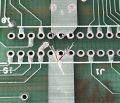
- To make the next step easier, the entire cartridge port can be desoldered from the board, providing you with much more room to work with (Fig. 1).
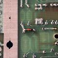
- Using a razor blade or other sharp tool, make a U or V-shaped cut on the board to isolate pin 24 from ground. The topside pad for pin 24 should resemble an arrowhead or teardrop when the trace cut has been complete (Fig. 2). Use a multimeter in continuity mode to ensure that pin 24 is no longer grounded.
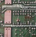
- Flip over the board so the components are upside-down. Solder the cathode (striped end) of a 1N914 diode to the upper pad (facing the rear) of resistor R26, then run a wire from the diode's anode to pin 24 of the cartridge port (Fig. 3).
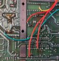
- Solder the cathode of a 1N914 diode to the upper pad of C13, with the anode going to the upper pad of C14 (Fig. 4).
- Solder a diode in parallel with R10. The cathode should be on the lower pad (facing the front) of R10 with the anode on the upper pad (Fig. 5).
- Solder a wire from the lower pad of L8 to pin 11 of the cartridge port.
- Take the assembled modification PCB and, using foam tape or double-sided tape, mount it in an area where it will not interfere with the RF shielding or case.
- Solder a wire from pin 30 of the cartridge port to the pad labeled "Pin 30" on the mod PCB.
- Solder a wire from the lower pad of C10 to the pad labeled "C10" on the mod PCB.
- Solder a wire from the lower pad of R11 to the pad labeled "R11" on the mod PCB.
- Solder a wire from the upper pad of R12 to the pad labeled "R12" on the mod PCB.
- Reassemble the 5200 to the point where it can be tested with the CX55. Note that the RF shielding is not required for testing and can be left out. If the test was successful, proceed with fully reassembling the 5200.
References
The original Atari service bulletin, which forms the basis for this procedure


