NES:Connector Pinouts
A/V Connector Pinout
Note: This connector is only available on the AV Famicom and a small handful of NES top loaders. It only carries composite video with dual mono audio, but does have the necessary pins present for S-video and RGBS outputs.
Main article:Nintendo Multi Out
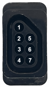
Controller Pinout
Note: Male is connector at the console. Female is connector at the controller. Diagram pictured is of the connector at the console end. This connector is only present on non-Japanese hardware and the AV Famicom. Wire colors correspond to the NES-001 controller port wires.
| Pin # | Description | Wire Color |
|---|---|---|
| 1 | GND | Brown |
| 2 | Clock | Red |
| 3 | Latch | Orange |
| 4 | Data | Yellow |
| 5 | 5V | White |
| 6 | D3 (port 2 only) / Unused (AV Famicom) | Blue |
| 7 | D4 (port 2 only) / Unused (AV Famicom) | Purple |
Famicom Cartridge Pinout
Note: Pins 1 through 30 are towards the front and numbered from left to right. Pins 31 through 60 are towards the back and also numbered from left to right. This table is oriented so the front of the port is facing left.
| Pin # | Name | Description | Pin # | Name | Description |
|---|---|---|---|---|---|
| 1 | GND | 31 | 5V | ||
| 2 | CPU A11 | 32 | M2 | CPU clock output | |
| 3 | CPU A10 | 33 | CPU A12 | ||
| 4 | CPU A9 | 34 | CPU A13 | ||
| 5 | CPU A8 | 35 | CPU A14 | ||
| 6 | CPU A7 | 36 | CPU D7 | ||
| 7 | CPU A6 | 37 | CPU D6 | ||
| 8 | CPU A5 | 38 | CPU D5 | ||
| 9 | CPU A4 | 39 | CPU D4 | ||
| 10 | CPU A3 | 40 | CPU D3 | ||
| 11 | CPU A2 | 41 | CPU D2 | ||
| 12 | CPU A1 | 42 | CPU D1 | ||
| 13 | CPU A0 | 43 | CPU D0 | ||
| 14 | CPU R/W | 44 | ROMSEL | Outputs the logical NAND gate of M2 and CPU A15 | |
| 15 | IRQ | 45 | 2A03 Audio Input | Inputs audio from the Famicom into the cartridge | |
| 16 | GND | 46 | Audio Output | Outputs mixed audio from the cartridge back into the Famicom | |
| 17 | PPU Read | 47 | PPU Write | ||
| 18 | PPU RAM A10 | 48 | CE | Connected to the PPU RAM | |
| 19 | PPU A6 | 49 | PPU A13 | ||
| 20 | PPU A5 | 50 | PPU A7 | ||
| 21 | PPU A4 | 51 | PPU A8 | ||
| 22 | PPU A3 | 52 | PPU A9 | ||
| 23 | PPU A2 | 53 | PPU A10 | ||
| 24 | PPU A1 | 54 | PPU A11 | ||
| 25 | PPU A0 | 55 | PPU A12 | ||
| 26 | PPU D0 | 56 | PPU A13 | ||
| 27 | PPU D1 | 57 | PPU D7 | ||
| 28 | PPU D2 | 58 | PPU D6 | ||
| 29 | PPU D3 | 59 | PPU D5 | ||
| 30 | 5V | 60 | PPU D4 |
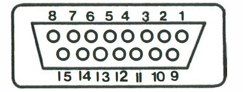
Famicom Expansion Pinout
Note: Male is connector at the console. Female is connector at the controller. Diagram pictured is of the connector at the controller end.
| Pin # | Description |
|---|---|
| 1 | GND |
| 2 | 2A03 Audio Out (note that this does not carry cartridge audio) |
| 3 | IRQ |
| 4 | D4 Controller 2 |
| 5 | D3 Controller 2 |
| 6 | D2 Controller 2 |
| 7 | D1 Controller 2 |
| 8 | D0 Controller 2 |
| 9 | Controller 2 OE |
| 10 | Digital Output 2 |
| 11 | Digital Output 1 |
| 12 | Digital Output 0 |
| 13 | D1 Controller 1 |
| 14 | Controller 1 OE |
| 15 | 5V |
FamicomBox Cartridge Port
Note: Pins 1 through 36 are on the top (front on the top loader) and numbered from left to right. Pins 37 through 72 are on the bottom (rear on the top loader) and also numbered from left to right. This table is oriented so the top of the port is facing left.
| Pin # | Name | Description | Pin # | Name | Description |
|---|---|---|---|---|---|
| 36 | 5V | 72 | GND | ||
| 35 | CIC to Motherboard | 71 | CIC Clock | ||
| 34 | CIC to Cartridge | 70 | CIC Reset | ||
| 33 | PPU D3 | 69 | PPU D4 | ||
| 32 | PPU D2 | 68 | PPU D5 | ||
| 31 | PPU D1 | 67 | PPU D6 | ||
| 30 | PPU D0 | 66 | PPU D7 | ||
| 29 | PPU A0 | 65 | PPU A13 | ||
| 28 | PPU A1 | 64 | PPU A12 | ||
| 27 | PPU A2 | 63 | PPU A10 | ||
| 26 | PPU A3 | 62 | PPU A11 | ||
| 25 | PPU A4 | 61 | PPU A9 | ||
| 24 | PPU A5 | 60 | PPU A8 | ||
| 23 | PPU A6 | 59 | PPU A7 | ||
| 22 | PPU RAM A10 | 58 | Unused | ||
| 21 | PPU Read | 57 | Unused | ||
| 20 | CPU A15 | 56 | PPU Write | ||
| 19 | Slot Index 3 | 55 | GND | ||
| 18 | Slot Index 2 | 54 | GND | ||
| 17 | Slot Index 1 | 53 | GND | ||
| 16 | Slot Index 0 | 52 | 5V | ||
| 15 | IRQ | 51 | 5V | ||
| 14 | CPU R/W | 50 | ROMSEL | Outputs the logical NAND gate of M2 and CPU A15 | |
| 13 | CPU A0 | 49 | CPU D0 | ||
| 12 | CPU A1 | 48 | CPU D1 | ||
| 11 | CPU A2 | 47 | CPU D2 | ||
| 10 | CPU A3 | 46 | CPU D3 | ||
| 9 | CPU A4 | 45 | CPU D4 | ||
| 8 | CPU A5 | 44 | CPU D5 | ||
| 7 | CPU A6 | 43 | CPU D6 | ||
| 6 | CPU A7 | 42 | CPU D7 | ||
| 5 | CPU A8 | 41 | CPU A14 | ||
| 4 | CPU A9 | 40 | CPU A13 | ||
| 3 | CPU A10 | 39 | CPU A12 | ||
| 2 | CPU A11 | 38 | M2 | CPU clock output | |
| 1 | GND | 37 | Unused |
NES Cartridge Port
Note: Pins 1 through 36 are on the top (front on the top loader) and numbered from left to right. Pins 37 through 72 are on the bottom (rear on the top loader) and also numbered from left to right. This table is oriented so the top of the port is facing left. Pins 16 through 19 and pins 52 through 55 are not physically present on the top loader.
An important thing to note about the NES cartridge port is that its pin pitch (the distance between pins) is actually 2.5 mm and is not the industry standard of 2.54 mm. Many clone consoles use the latter and tend to have connection problems because of this.
| Pin # | Name | Description | Pin # | Name | Description |
|---|---|---|---|---|---|
| 36 | 5V | 72 | GND | ||
| 35 | CIC to Motherboard (NES-001) / Unused (NES-101) | 71 | CIC Clock (NES-001) / PPU D4 (NES-101) | ||
| 34 | CIC to Cartridge (NES-001) / Unused (NES-101) | 70 | CIC Reset (NES-001) / 5V (NES-101) | ||
| 33 | PPU D3 | 69 | PPU D4 | ||
| 32 | PPU D2 | 68 | PPU D5 | ||
| 31 | PPU D1 | 67 | PPU D6 | ||
| 30 | PPU D0 | 66 | PPU D7 | ||
| 29 | PPU A0 | 65 | PPU A13 | ||
| 28 | PPU A1 | 64 | PPU A12 | ||
| 27 | PPU A2 | 63 | PPU A10 | ||
| 26 | PPU A3 | 62 | PPU A11 | ||
| 25 | PPU A4 | 61 | PPU A9 | ||
| 24 | PPU A5 | 60 | PPU A8 | ||
| 23 | PPU A6 | 59 | PPU A7 | ||
| 22 | PPU RAM A10 | 58 | PPU A13 | ||
| 21 | PPU Read | 57 | CE | ||
| 20 | EXP 4 (NES-001) / Unused (NES-101) | Pin 38 of expansion port | 56 | PPU Write | |
| 19 | EXP 3 | Pin 39 of expansion port | 55 | EXP 5 | Pin 10 of expansion port |
| 18 | EXP 2 | Pin 40 of expansion port | 54 | EXP 6 | Pin 9 of expansion port |
| 17 | EXP 1 | Pin 41 of expansion port | 53 | EXP 7 | Pin 8 of expansion port |
| 16 | EXP 0 | Pin 42 of expansion port | 52 | EXP 8 | Pin 7 of expansion port |
| 15 | IRQ | 51 | EXP 9 (NES-001) / Unused (NES-101) | Pin 6 of expansion port | |
| 14 | CPU R/W | 50 | ROMSEL | Outputs the logical NAND gate of M2 and CPU A15 | |
| 13 | CPU A0 | 49 | CPU D0 | ||
| 12 | CPU A1 | 48 | CPU D1 | ||
| 11 | CPU A2 | 47 | CPU D2 | ||
| 10 | CPU A3 | 46 | CPU D3 | ||
| 9 | CPU A4 | 45 | CPU D4 | ||
| 8 | CPU A5 | 44 | CPU D5 | ||
| 7 | CPU A6 | 43 | CPU D6 | ||
| 6 | CPU A7 | 42 | CPU D7 | ||
| 5 | CPU A8 | 41 | CPU A14 | ||
| 4 | CPU A9 | 40 | CPU A13 | ||
| 3 | CPU A10 | 39 | CPU A12 | ||
| 2 | CPU A11 | 38 | M2 | CPU clock output | |
| 1 | GND | 37 | System Clock |
NES Expansion Port
Note: This connector is only found on the original front loading NES.

