SNES:Digital Audio (SPDIF) Mod
Jump to navigation
Jump to search
Info
There are two types of audio that are not compatible with the digital audio mod:
- Super Game Boy adapters create their own audio, so Game Boy audio can only be passed through the analog-out of the SNES, not digital.
- Any homebrew game that uses the MSU Audio programming of the SD2SNES rom cart will not work with the digital audio mod. All other games work and sound perfectly via the SD2SNES, but (much like the SGB), MSU audio is created in the SD2SNES cart, not the SNES, bypassing the internal sound chips.
SNES SPDIF Digital Audio Mod
- Before starting, you should choose a location for the digital audio board. Most people prefer doing it through the plastic next to the RF port, but pretty much anywhere will work.
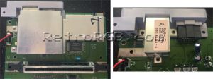
- Next, completely disassemble the SNES and remove the motherboard. You’ll also need to remove the heatsink and expose the RF module.
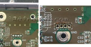
- Now, turn the motherboard over and locate the 4 pins for the RF module. You’ll need to desolder all 4.
- Next, use an x-acto knife or sharp blade to cut the RF hole into a square. Do not cut the hole any higher then it already is, only cut down and to the sides. If you make the hole too high, you won’t be able to fit the optical audio cable. Also, you’ll want to make it snug; just big enough for the SPDIF connector to fit through. Using a file to finish the hole is highly recommended.
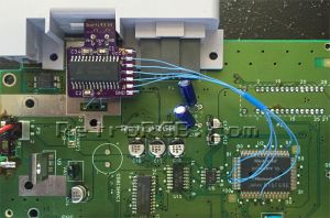
- After it fits, use super glue or epoxy around the inside edges of the digital audio connector to secure it in place. Make sure to mount the board with the chip & solder pads facing up.
- Next, you’ll want to connect power and ground. The easiest place to find these is from the 4 RF pins we desoldered earlier.
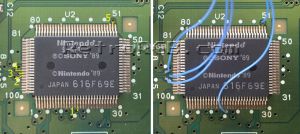
- Next, you’ll want to find the audio chip and solder wires to the following 5 points on the motherboard (if your system is not a 1CHIP, either solder directly to the S-APU chip, or check the "Non-1CHIP Mod Points" sections).
- After soldering, test the digital audio, and if it works, reassemble the SNES. You're done!


