Neo Geo:UNIVERSE BIOS (UniBIOS)
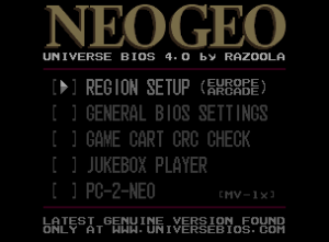
The UNIVERSE BIOS (UniBIOS for short) is a custom bios that can be used on MVS and AES hardware. The main reason for installing UniBIOS is to change the region and mode between Arcade and Console modes on boot, but it adds a multitude of features. You can either purchase an EEPROM with UniBIOS preloaded, or you can download UniBIOS and flash it to your own blank EEPROM.
| UniBIOS is also available for the Neo Geo CD, but it's in an experimental state. |
Features
- The ability to quickly and easily change operation from MVS to AES. Play your favorite games as the home console version enabling all the extra gameplay options that come with some games.
- The ability to quickly and easily change country region (great for games that disable blood under USA region).
- Access to the DEBUG DIP's and DEVELOPER mode.
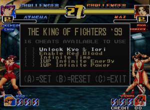
- In-game cheat engine with built-in codes as well as the ability to patch any memory address.
- Hiscore saving support on AES hardware (memory card required).
- PICKnMIX (161-in-1 cart required), see menu for more information.
- Jukebox player to listen to game music directly from games.
- A ROM CRC32 check where you can confirm a game's program ROM are good.
- True USA region support (correct coin display on bottom left and right of screen in the same way a true USA BIOS does).
- Arcade VS-MODE support which is known to be in the version 6 JAPAN bios. Turn this feature on via hard dip 2.
- PC-2-NEO which gives the ability to upload and download data from the system using a cable which can be easily built.
- Remapping of coin switches to select buttons and visa versa. This allows a SNK joypad pad to do everything.
- Once region and operation mode is set the BIOS will remember settings until you change them again (memory card required on AES hardware for this to work).
- Access to the standard Memory Card Utility no matter what Mode the BIOS is in (one could never access this menu with the normal MVS BIOS).
- Access to Test Mode on boot without the need of wiring the Test Mode JAMMA pins or fiddling with DIP's.
- Enhancements to the TEST MODE menu and hardware test screens.
- Hide DEV slot check messages (and red warning screens) from some games when running on MVS hardware in console mode or AES hardware in arcade mode.
- Look at internal memory with the built in memory viewer. This is handy for tracking faults with slots that don't work (multislot hardware) or carts that simply won't start.
- The ability to soft reboot the system without the need of powering off and on.
- Allows full fatalities in the AES unfixed cart of Samurai Shodown V Special.
Installation
Socketed BIOS Install
These models have a socketed BIOS that can be popped out using your fingers and replaced with a UniBIOS EEPROM:
- MV-1
- MV-1A(CH)
- MV-1F(S/T)
- MV-1FZ
- MV-(2F/4F/6F)
Soldered BIOS Install
The following models do not have a socketed BIOS:
- All AES models
- Front-loader Neo Geo CD
- MV-1AX
- MV-1ACHX
You can use one of the following methods to install UniBIOS.
Piggyback Installation
You will need a 15K 1/4 watt carbon resistor and some wire. Optionally, you can follow the same instructions but using a 40 pin DIP socket instead to make chip replacement easier in the future if you ever want to update the chip.
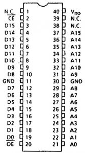
Refer to this image of the pinout of the BIOS:
- Locate the BIOS chip. The chip will normally have '531024' written somewhere on it.
- Locate pin 2 on the chip. It is the second pin going counter-clockwise from the half circle cut in the chip. Lift or cut the pin (as close to the board as possible) and bend it to be parallel with the motherboard.
- Locate pin 2 on the UniBIOS chip and bend it so it is parallel with the floor, noting the half circle on the chip.
- Place the chip on top of the existing BIOS chip and make sure the pins are all aligned and overlapping. Pin 2 of each should not be touching each other.
- Solder all pins from the UniBIOS chip and the existing BIOS chip together (aside from pin 2) and avoid bridging any neighboring pins.
- Solder the resistor to pin 2 of the original BIOS chip and the other end to pin 40 (the first pin going clockwise from the half circle). The socket, original BIOS, and resistor should all be soldered together at pin 40.
- Solder one end of a wire to pin 2 of the UniBIOS chip and the other to pin 20 (joining it to both the old and new BIOS chips).
- If using a socket, push the new UniBIOS chip into the socket, ensuring it is orientated correctly.
- Power on the console without a game inserted. You should be presented with a blue screen if successfully installed.
Direct Replacement
- Desolder the existing BIOS chip. The chip will normally have '531024' written somewhere on it.
- Solder the new UniBIOS chip in its place, ensuring it is orientated correctly.
- Optionally, you can follow the same instructions but using a 40 pin DIP socket instead to make chip replacement easier in the future if you ever want to update the chip.
Other Models Install
The following models do not have a socketed BIOS and use a different sized chip than others:
- Top-loader Neo Geo CD
- MV-1B
- MV-1C
The installation is a bit different, as you will need to disable the onboard BIOS, solder two wires, snap the NewBiosMasta adapter PCB in place, then plug the new BIOS in.
The NeoBiosMasta is a PCB with a socket that clips onto the existing BIOS on the motherboard. This methods still requires the soldering of two wires, but greatly simplifies the process. It can be purchased from various places or you can make your own via the open-source files on OSHpark. There is also a variant with a virtual memory card (VMC). If you have a Neo Geo CD, you will need a "NeoBiosMasta CD".
MV-1B
Clear diagrams of the below instructions can be found here.
- Lift pins 2 and 20 of the original BIOS labelled "SP1". Pin 1 is marked with a circle indent on top of the chip.
- Bridge pins 1 and 2.
- Solder a wire from the pad below pin 2 to the
CEpad on the NeoBiosMasta. - Solder a wire from the pad below pin 20 to the
OEpad on the NeoBiosMasta.
MV-1C
Clear diagrams of the below instructions can be found here. An installation video can be found on ModzvilleUSA's channel.
- Lift pins 10 and 12 of the original BIOS labelled "SP1". Pin 1 is marked with a circle indent on top of the chip.
- Solder a wire from pin 10 to pin 21.
- Solder a wire from the pad below pin 10 to the
CEpad on the NeoBiosMasta. - Solder a wire from the pad below pin 21 to the
OEpad on the NeoBiosMasta.
Usage


