Atari 5200:Ultimate Atari Video Mod (UAV) Board
The Brewing Academy's Ultimate Atari Video (UAV) board was originally developed by Bryan Edewaard as a universal mod board to allow composite and s-video output on various Atari systems. In the case of the Atari 5200, this board can be installed along the CD4050 chip to retain RF output or it can be used in place of the CD4050 chip for a simpler install.
The latest version of the official manual can be downloaded from The Brewing Academy's site or an archived copy can be found here - though it just directs you to use these instructions by Ivory Tower Collections.
Ivory Tower Collections also has great UAV installation videos for the 2-port Atari 5200 and the 4-port 5200.
Jumper Configuration
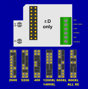
Configure the jumpers as shown in the picture below for the 5200. If your kit has pins and jumpers, you can insert them as shown. Otherwise, put a large blob of solder on each required pin, then drag them into each other to make the necessary bridges.
Mounting Output Jacks
Decide on a place to drill holes and mount your s-video, composite, and left/right audio jacks.
It's recommended to use the expansion bay panel found in the back-left of the console, as that port was never used for any official products. You can use your fingers to pop this panel out, put a strip of masking tape over it, and measure and mark where you'd like the jacks to be. Keep in mind that some cable plugs are thick and will require extra space between the jacks. Drill the holes just large enough that you can stick the back end of the jacks through them.
Clearing Wire Route
Due to the metal RF shield covering any potential path for wires to get to the outside of the case, you will either need to bend the RF shield, use metal shears to cut a hole in it, or — if you decided to mount the jacks on the expansion bay panel — you can gently (without bending the shield) pop off the piece of the RF shield near the expansion bay.
Installing the UAV
(Option 1) Removing RF Output
If you have a 2-port model or (need to find how to determine if your 4-port model is compatible), you have the option to completely remove the CD4050 chip via hot air or desoldering iron. From here, you can install the socket pins on the motherboard and plug the UAV directly in.
(Option 2) Preserving RF Output
- Piggyback method
- Desolder and mount on top method
Audio Output
The UAV board does not include any handling for audio, so you will need to solder up a connection to enable mono audio for the left/right audio jacks. The Atari 5200 is not capable of stereo audio.
- You will need:
- 10µF capacitor
- 2Kohm resistor
- Solder a 10-12 inch long strand of wire to the negative lead of the capacitor.
- Solder the resistor to the positive lead of the capacitor.
- Solder the other end of the resistor to the north leg of the R50 resistor on the motherboard.
- Solder the 10-12 inch long strand of wire to the center of one of the audio jacks.
- Solder a wire from the center of one audio jack to the other.
Troubleshooting
- If for some reason you are only getting a black and white picture and all of your connections look fine and have continuity, you can try soldering to the south side of the very top-right resistor on the motherboard with a 1µF capacitor in series with the negative lead being connected to the audio output jacks. Reportedly, the resistor next to it also works.
