SNES:THS7314 RGB Bypass
Jump to navigation
Jump to search
Mitch1256

This page shows how to use a pre-made RGB Amp to bypass the SNES Mini's internal RGB amp and uses one based off a THS 7314. The amp you purcahse may not look exactly like the one pictured, however as long as the amp is a THS 7314, the installation is the same.
Tools / Parts Needed:
- You'll need a few tools for this mod:
- #Pre-Made THS 7314 Amplifier Board
- #Basic soldering skills.
- #SNES RGB cable.
- #The 4.5mm tool that opens the SNES
- #Philips head screwdriver
- #Soldering iron / solder
- #Thin gauge wire
- #Three 1.2k resistors, the lowest tolerance possible: http://www.mouser.com/ProductDetail/KOA-Speer/MF1-4DCT52R1201F
RGB Mod:
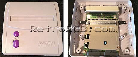
- Open the console and remove the board (pretty much just unscrew everything):
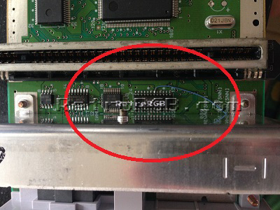
- After opening the SNES Mini, look for the S-RGB chip between the cartridge slot and the heat sink:
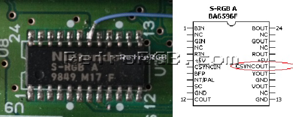
- Remove the heatsink and solder a wire to pin 18, which is csync:
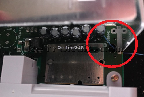
- Run that wire through the hole near the heatsink, but make sure when you replace the heatsink that it is not pinched:
- Trim any slack from the wire and solder the cable to pin 3 of the multi-out:
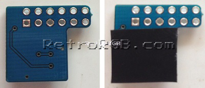
- Prepare the pre-made THS7314 amp. The bottom of the amp board has no components on it, however it is recommended to add a piece of non-conductive tape to the bottom, just to be sure. If nothing else, it won't hurt:
- Next, solder the amp to the multi-out, making sure it slides over all the pins (note the csync cable, which was installed before the mod):
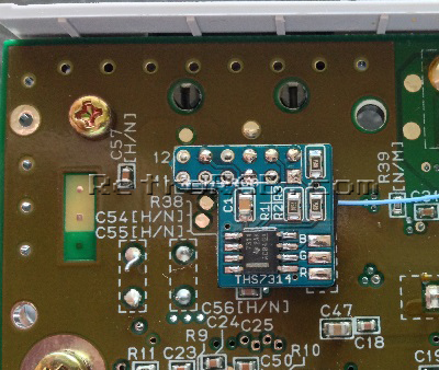
- Some SNES Mini's come from the factory with the two ground pins soldered together. If your system has this, you could either cut the solder in the middle (be _really_ careful not to damage the pins), or use a solder-removing method (de-soldering iron, solder wick, etc):
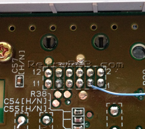
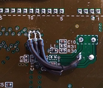
- Next, locate the following spot on the motherboard:
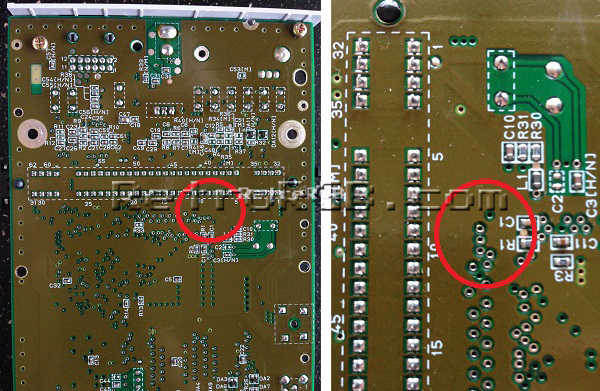
- Solder thin wire to the following points to get RGB. Make sure the stripped wire isn't too long, as it will stick out the top of the motherboard:
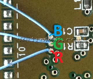
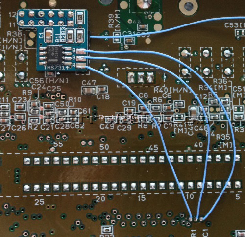
- Cut the wires to length and solder them to the corresponding RGB pads on the amp. Your installation should now look like this (click for full-size):
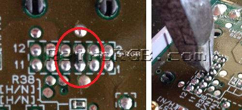
- Then, solder 1.2k Ohm resistors to the same places you'd get RGB from the board. Make sure to solder the RGB wires between the resistors and the board.
- Finally, solder the other side of all three resistors to ground (click for full-sized):
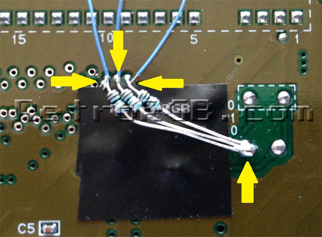
- It's recommended to use shrink tubing on each resistor! I used tape to cover the components, but only because it made the above picture easier to see. For your installation it would be much better to shrink tube each one (thanks to John for his pic):
- \For beginners, it must seem strange to tie all the video lines to ground, but as long as the video lines are on the motherboard-side of the resistor, it will work to properly adjust the input brightness to the exact level the SNES Mini should be outputting.
- A note for SFC Jr owners: I suggest first trying the mod without the brightness-attenuating resistors. I've only personally tested one SFC Jr, but found that using the same resistors as the SNES Mini worked best. I've had other people report that no resistors at all is the best choice and Alex (aka ArcadeTV) said he needed these to get the proper output from his SFC Jr:
- [1]


That’s it...not too hard of a mod and the picture quality is amazing!!! Check out the difference from an average (non-1CHIP) SNES 1 to a SNES Mini:
