LaserActive:PAC-S10 - Various Issues and Solutions
This page details several faults discovered while servicing various PAC-S10/S1 modules and their solutions.
Post-Recap Short Circuit Check
After performing any capacitor replacement work, it is imperative to check the three voltage rails (+5, +8, -8) for short circuits. If there is a short circuit on any of these rails, it will damage the CLD-A100 player. Both the MAIN and SUB boards have fuses that are labeled with the voltages they protect on the back side of each board. Check that these are not shorted to Ground on BOTH boards. Also note that the SUB board has two grounds - one for digital and one for audio. The fused 5V rail is referenced to the digital ground and can be checked by measuring continuity to the ground on C506.
BIOS Freezes at Power On
This issue has more than one root cause.
No Mega LD/CD Logos appear - PCM Chip Select Line Missing
Due to its proximity to C310, electrolytic fluid corrosion could have severed the PCM Chip select line to the SSUB connector, causing a bus collision, as the chip select line on the PCM ASIC has no pulldown/up to counteract a floating state. First, ensure the via to the left of C310 has continuity to IC28, pin 89. Then, check if it has continuity to pin 31 of the SSUB connector. If continuity is missing between either of these, restore it.
- ==Blank Screen on Power Up - Cartridges and BIOS do not load==
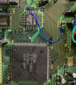
- Restore the signal by reconnecting Pin 32 to the plated via next to the "40" text, adjacent to the BIOS EEPROM.
Missing/No Sound In Certain Games, Cannot boot Master System games
This is due to a missing data line from the Z80 CPU to the Sega 315-5660 ASIC. C129 is near the lines for D13-15 vias from the Z80 to the 5660 and C111 is near D5-7, increasing the probability of damage from extended exposure to leaked electrolytic fluid. First discover where the signal is lost and then jump the signal to the appropriate trace.
Horizontal Color Smearing
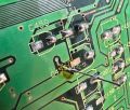
The PAC-S10/S1 employs separate voltage regulators to bias the emitter follower buffers for the RGB signals. The trace that provides voltage to the RED signal buffer is adjacent to C453, which is prone to heavy leakage and can sever the +5V regulated voltage line. This repair can be accomplished by using a thin gauge wire/component lead to jump the top side metal to the bottom side, or a wire can be used to directly jump the signal via the component pads as shown.


