Saturn:Digital Audio (SPDIF) Mod
Jump to navigation
Jump to search
There are two boards that will allow you to obtain digital audio: Will's Sega Saturn SPDIF Kit and the Pep Audio board by citrus3000psi. There are some reports of issues with the Pep Audio board, so you may want to opt for Will's kit.
Will's Sega Saturn SPDIF Kit
Required Parts
- Will's Sega Saturn SPDIF Kit
- If using TOSLINK:
- TX178A (TOSLINK port) and TOSLINK PCB by citrus3000psi OR TOSLINK battery door.
- If not using a TOSLINK port, you will need your own jack.
Installation
The Sega Saturn has 3 types of DAC Chips depending on the motherboard version number, locate the DAC chip on your motherboard to find which one you have.
| Signal | TDA1386T | PCM1710 | PCM1717E | YMF292 (SCSP) |
|---|---|---|---|---|
| EMPH: Emphasis | 13 | 27 - C62 | C62 (North Pad) | |
| RST: Reset | 15 | 25 | Pin 18 on chip | |
| ILRCK: Word Clock | 5 | Pin 1 (TP112) | Pin 4 (TP112) | 63 |
| ISCLK: Bit Clock | 4 | Pin 3 (TP111) | Pin 6 (TP111) | 62 |
| SDIN: Audio Data | 6 | Pin 2 (TP110) | Pin 5 (TP110) | 61 |
| OMCK: Master Clock | 12 | Pin 5 (TP113) | Pin 1 (TP113) | 64 |
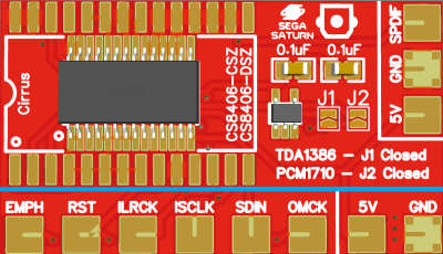
- Connect wires from the mod kit board solder points (under the blue line) to the following points to the Sega Saturn DAC chip using the table below to find the corresponding leg number on the DAC chip.
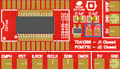
- If your Saturn has the TDA1386 DAC, bridge jumper
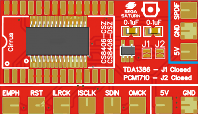
J1. If your Saturn has the PCM1710 or PCM1717E DAC, bridge jumperJ2. - Connect the SPDIF, GND, and 5V pads on the PCB to the SPDIF PCB and find a suitable mounting location for the jack (if not using the battery door).
Pep Audio Board (SPDIF or TOSLINK)
Original guide adapted from a post by citrus3000psi. A good writeup about this mod can be found on FireBrandX's site.
This tutorial assumes you have a TDA1386T DAC chip in your Saturn.
Required Parts
Parts are dependent on if you want SPDIF or TOSLINK:
- Pep Audio 1.2 PCB by citrus3000psi
- TC7W04FK chip
- TC9231N chip
- Two 0.1uF capacitors (0603 size)
- If using TOSLINK:
- TX178A (TOSLINK port) and SPDIF PCB by citrus3000psi OR TOSLINK battery door.
- If not using a TOSLINK port, you will need your own jack.
Installation
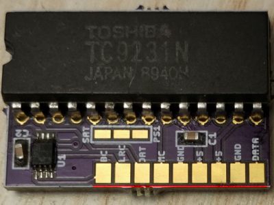
- There exists an issue (as noted by FireBrandX) with the Pep Audio PCB where some of the boards have extra ground fill in front of the pins and cause shorts. Use a multimeter to make sure none of the pads (GND excluded) have continuity to GND. If you do find continuity, you will need to use a hobby knife to cut off the area marked in red below:
- Assemble the Pep Audio PCB.
- Bridge the "SAT" pad on the Pep Audio PCB to the pad next to it.
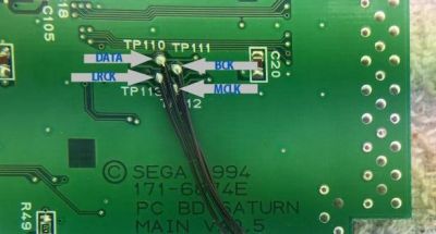
- On the back of the motherboard, solder these points to the Pep Audio board.
DATAon motherboard toDATon Pep Audio PCB (notDATA!).BCKon motherboard toBCon Pep Audio PCB.LRCKon motherboard toLRCon Pep Audio PCB.MCLKon motherboard toMCon Pep Audio PCB.
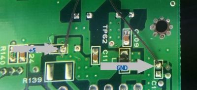
- Solder +5V to pin 7 of the TC9231N.
- Connect the output jack:
- If using a TOSLINK port, connect +5V and GND to it. Also connect
DATA(notDAT!) on the Pep Audio PCB to theInon the TOSLINK port. - If using your own SPDIF port, connect
DATAon the Pep Audio PCB to the data pin and GND to GND.
- If using a TOSLINK port, connect +5V and GND to it. Also connect
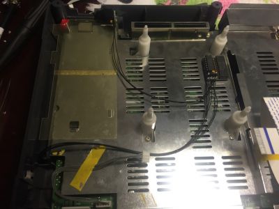
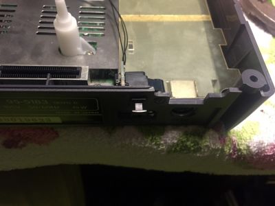
- Mount your SPDIF or TOSLINK PCB (if not using the battery door). This is one suggested location, but it may depend on what devices you may have installed in your unit.
- Mount your external jack. This is one suggested location, but may require trimming of the case.
