N64:Power Supply Repair
Jump to navigation
Jump to search
| Power supplies have live voltage 100 - 230V AC, please do not open a powersupply that was recently powered and never debug or repair a powersupply that is plugged in. |
PAL Power Supplies
General things to check
- Thoroughly check for cold/broken solder joints, PCB cracks, or damaged PCB traces. Repair faults.
- If voltages are off (3.3V - 3.6V and 10.8V - 12V are normal), check secondary caps, sometimes pads are no longer connected to the pcb.
Type: M / Matsushita ETYNT184SE / NPY184SE
- Check Fuse (F101) for continuity. If open:
- Check for shorts between all contacts on bridge rectifier (D101). if any shorts
- Remove bridge rectifier.
- Check for shorts on output side of bridge rectifier (or C103) again. ~500 Ohms are normal. If short is gone, replace bridge rectifier:
- - 1:1 replacement: Shindengen S1WB(A)60-7101 (poor availability)
- - Tested alternative: e.g. Diodes Incorporated DF10M (package is too short so the pins need to be bent outwards a bit)
- - generally any 600V/1A type should be equivalent.
- If there is still a short with the bridge rectifier removed, measure resistance between pins of power MOSFET (Q101); all combinations should either yield ~500-600 Ohms or Open depending on polarity. If there are any shorts, replace power MOSFET:
- - 1:1 replacement: Toshiba 2SK2700 (poor availability)
- - Tested alternative: STMicroelectronics STF5NK100Z TO-220FP variant
- Recheck rectified primary side; if short is gone (500 Ohms are expected), finally replace the fuse.
- - 1:1 replacement: unknown - Tested alternative: Littelfuse 37212000001
- - generally any 5mm radial 2A/T(slow blow) 250VAC should work well.
- Check for shorts between all contacts on bridge rectifier (D101). if any shorts
- Check F201 and F202 on secondary output, replace if necessary. Any 5A (F201) or 2.5A (F202) axial fuse should work as a replacement.
- Test electrolytic capacitors, replace only if necessary. Use high temperature types (105°C). Low ESR is not required (and might cause high rush currents) for C103.
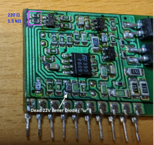
- If output voltages are still missing, check the daughterboard: Most commonly the two 0603 SMD resistors in the top left corner, which are usually covered with gunk next to the 3.3V rectifier (D201), can fail open. Expected resistance values are:
- Upper resistor: 220 Ohms
- Lower resistor: 1.5 kOhms
- If measured resistance is much higher or open on either of the resistors, replace it (in fact replace both for good measure; the parts don’t seem to like to make contact with the silicone gunk).
- If still no good voltage, you might try checking the Zener diodes on the daughterboard; they are silver painted plastic packages with the voltage printed on the package.
Type: N1,2,3,4,6 JRC NJD-4662
- Check Fuse (F1 and TF1) for continuity. If open:
- Check for shorts between all contacts on bridge rectifier (DS1). if any shorts
- Remove bridge rectifier.
- Check for shorts on output side of bridge rectifier (or C103) again. ~500 Ohms are normal. If short is gone, replace bridge rectifier:
- - 1:1 replacement: Shindengen S1VB60 (poor availability)
- - Tested alternative: e.g. Diodes Incorporated KBP208G (package is too short so the pins need to be bent outwards a bit)
- - generally any 600V/1A type should be equivalent.
- If there is still a short with the bridge rectifier removed, measure resistance between pins of power MOSFET (TR1); all combinations should either yield ~500-600 Ohms or Open depending on polarity. If there are any shorts, replace power MOSFET:
- - 1:1 replacement: NEC 2SK2137 (poor availability)
- - Tested alternative: STMicroelectronics STF5NK100Z TO-220FP variant
- Recheck rectified primary side; if short is gone (500 Ohms are expected), finally replace the fuse.
- - 1:1 replacement: unknown - Tested alternative: Littelfuse 37211600001
- - generally any 5mm radial 1.6A/T(slow blow) 250VAC should work well.
- Check for shorts between all contacts on bridge rectifier (DS1). if any shorts
- Check F2 and F3 on secondary output.
- Resolder connection of the attachment pcb (PWB2).
Type: N5 JRC NJD-5168
- Check Fuse (F1 and TF1) for continuity. If open:
- Check for shorts between all contacts on bridge rectifier (DS1). if any shorts
- Remove bridge rectifier.
- Check for shorts on output side of bridge rectifier (or C103) again. ~500 Ohms are normal. If short is gone, replace bridge rectifier:
- - 1:1 replacement: Shindengen S1VB60 (poor availability)
- - Tested alternative: e.g. Diodes Incorporated KBP208G (package is too short so the pins need to be bent outwards a bit)
- - generally any 600V/1A type should be equivalent.
- If there is still a short with the bridge rectifier removed, measure resistance between pins of power MOSFET (TR1); all combinations should either yield ~500-600 Ohms or Open depending on polarity. If there are any shorts, replace power MOSFET:
- - 1:1 replacement: Mitsubishi FS4KM-12 (poor availability)
- - Tested alternative: STMicroelectronics STF5NK100Z TO-220FP variant
- Recheck rectified primary side; if short is gone (500 Ohms are expected), finally replace the fuse.
- - 1:1 replacement: unknown - Tested alternative: Littelfuse 37211600001
- - generally any 5mm radial 1.6A/T(slow blow) 250VAC should work well.
- Check for shorts between all contacts on bridge rectifier (DS1). if any shorts
- Check F2 and F3 on secondary output.
- Resolder connection to the 2 ceramic attachment pcbs (IC1 & IC2)
Type: K
- Check Fuses (F1 and F2) for continuity.
- Check F102 on secondary output.
- Check P1 for broken solder joints
