AV:Sync Stripper
This page lists different options to obtain a sync stripper. Please note: You do not need a sync stripper for SCART equipment, but some monitors and BNC switches might require them. Please only use one if you know for a fact you’ll need it.
Generally, a sync stripper may be required if:
- You are using luma sync or sync on composite video with an Extron Crosspoint.
- You are using a NEC XM29 or similar CRT TV.
Creating your own Sync Stripper
You can wire up a small board to use an LM1881 chip to "strip" the sync information from composite video, for use in an RGBs video signal.

Please note that the LM1881 outputs TTL-level sync. If you're going into a device that's expecting 75 ohm video-level sync (such as ALL SCART equipment), then you'll need to add a 470ohm resistor to the output line. For more information on sync, see the Types of Sync page.
Required Materials
- Soldering iron / solder
- Perfboard
- LM1881M chip, the SOIC version
- One 680K resistor
- Two 0.1uf Capacitors
- One 470 ohm, 1/4 watt resistor (if 75 ohm CSYNC output is needed)
Board Assembly
You can solder the components together directly, but it's recommended to use perfboard as shown in this example to make the circuit.
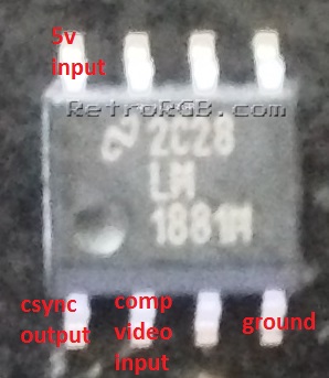
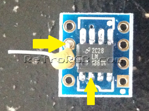
- This is the main LM1881M chip you'll be using (surface-mount, SOIC version) and it's relevant pins:

- Start by adding solder to both the chip legs and the pads on the board.
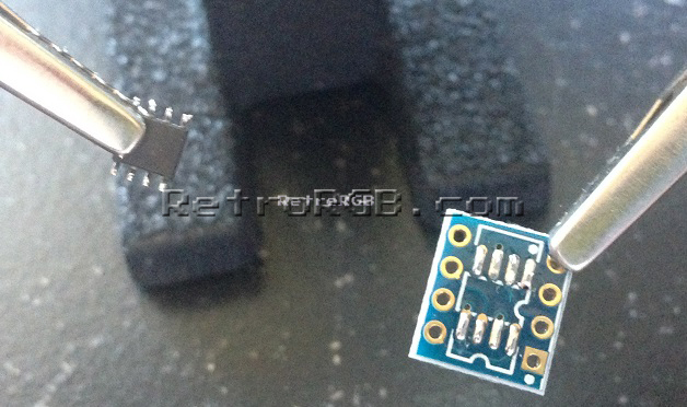
- Use pliers or tweezers to hold the chip while you mount it to the board.
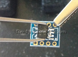
- When checking, make sure to touch the pin where it enters the chip, not near the bottom where you may accidentally be making contact with the circuit board's pads. Then, touch the other tester to the pad that matches it's input. If a connection isn't made, you could try adding more solder to the joint between the pad and pin:
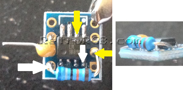
- Add a 0.1uf capacitor to the hole that corresponds with pin 2 (composite video in) on the LM1881M. Use a multimeter to double check that the hole on the board matches the pin on the chip:
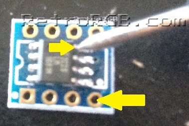
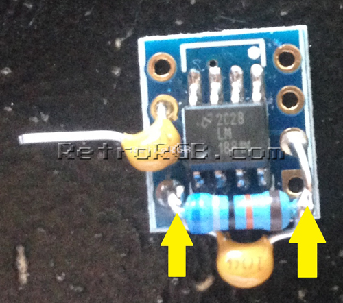
- Add a 680K resistor to the holes corresponding to the arrows below, again using a multimeter to double check the holes to pins between the chip and board. Also, make sure that the resistor isn't touching any of the pins on the chip, or touching the other holes on the board. This one is run above the board to ensure it's not touching:
- Solder a 0.1uf capacitor to the resistor. Solder it as close to the resistor itself as possible, to make sure it's not touching anything else, or touching to board's pads.


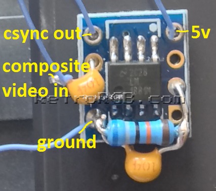
- Solder power and ground, as well as composite video in / CSYNC out:
- After you're done, it's good to cover the circuit with heatshrink tubing, so you won't risk shorting it out (or anything else around it).
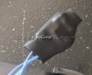


Overall, it's pretty easy to make and is a bit smaller then soldering it directly to the chip. The whole set can fit inside a VGA or SCART head for use with equipment that requires TTL-level voltage with a much cleaner look: 
75 Ohm CSYNC Output
Please note that this guide shows you how to build the sync stripper circuit; it does NOT talk about use case scenarios. If you're plugging this into any SCART device, then you'll need to add one 470 ohm, 1/4 watt resistor to attenuate the output to 75 ohm video standards. Many RGB monitors accept a wide variety of sync signals, including the TTL sync that this circuit outputs. If you'd like to be safe, just add the extra resistor; it's literally as easy as just soldering it to the CSYNC output pin.