Genesis:Triple Bypass Mod Model 3 VA1: Difference between revisions
Jump to navigation
Jump to search
(Changed structure to match the VA2 page. Added text for Warnings and Tools Required sections.) |
No edit summary |
||
| Line 1: | Line 1: | ||
This document will serve as clear | This document will serve as clear step-by-step instructions on installing the 3BP on the Genesis Model 3, revision VA1. | ||
== Warnings == | == Warnings == | ||
| Line 20: | Line 20: | ||
== Installation == | == Installation == | ||
[[File:Genesis_3_VA1_3BP_Top_Modded.jpg|200px|thumb|The top of the motherboard post-modification.]] [[File:Genesis_3_VA1_3BP_Bottom_Modded.jpg|200px|thumb|The bottom of the motherboard post-modification.]] | |||
# Start by removing the shell from your console. Remove the 4 screws at the bottom then turn it back upright and lift off the top shell. Remove the screws on the metal shielding and lift the shield off. Next, remove the 2 screws on the sides of the cartridge slot. Now you can lift the motherboard out of the bottom half of the shell. | |||
# Mount the bypass board on the top of the motherboard. The recommended spot is on the right-hand side on the large solder joints sticking up. | |||
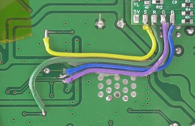
[[File: | # Solder wires from the video signals (RGBS) pads on the bypass board to the vias shown here. [[File:Genesis 3 VA1 3BP RGBS.png]] | ||
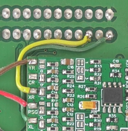
# Solder wires from the audio signals (YL/YR/PSG) pads on the bypass board to these resistors on the bottom side of the motherboard, snaking the wires through the controller ports to the top side of the motherboard. <br> [[File:Genesis 3 VA1 3BP Controller Ports.png]] | |||
# Solder wires from the audio signal output (XL/XR) pads on the bypass board to the cart connectors pins B1 (XL) and B3 (XR). <br> [[File:Genesis_3_VA1_3BP_XL_XR.png]] | |||
[[File: | |||
[[File: | |||
Revision as of 03:33, 25 October 2022
This document will serve as clear step-by-step instructions on installing the 3BP on the Genesis Model 3, revision VA1.
Warnings
Please read the below warnings before proceeding!
- This guide expects you to have a basic understanding of how to open up your Genesis Model 3 and to have basic soldering skills.
- This mod permanently alters your device.
- This mod should not be done by a beginner and is considered intermediate/advanced.
- Make sure power is disconnected before proceeding.
- After performing this mod you will no longer be able to use composite. You’ll be required to use RGB (or HD Retrovision) cables from this point forward.
- Proceed at your own risk!
Tools required:
- Flush cutters
- Snips
- Soldering iron
- Solder
- Flux
- Solder wick
- 28 or 30 AWG wire
Installation


- Start by removing the shell from your console. Remove the 4 screws at the bottom then turn it back upright and lift off the top shell. Remove the screws on the metal shielding and lift the shield off. Next, remove the 2 screws on the sides of the cartridge slot. Now you can lift the motherboard out of the bottom half of the shell.
- Mount the bypass board on the top of the motherboard. The recommended spot is on the right-hand side on the large solder joints sticking up.
- Solder wires from the video signals (RGBS) pads on the bypass board to the vias shown here.
- Solder wires from the audio signals (YL/YR/PSG) pads on the bypass board to these resistors on the bottom side of the motherboard, snaking the wires through the controller ports to the top side of the motherboard.

- Solder wires from the audio signal output (XL/XR) pads on the bypass board to the cart connectors pins B1 (XL) and B3 (XR).