LaserActive:PAC-S10 - Various Issues and Solutions: Difference between revisions
No edit summary |
|||
| (12 intermediate revisions by the same user not shown) | |||
| Line 1: | Line 1: | ||
This page details several faults discovered while servicing various PAC-S10/S1 modules and their solutions. | This page details several faults discovered while servicing various PAC-S10/S1 modules and their solutions. | ||
==Post-Recap | ==Partial Troubleshooting Schematic== | ||
After performing any capacitor replacement work, it is imperative to check the three voltage rails (+5, +8, -8) for short circuits. If there is a short circuit on any of these rails, it will damage the CLD-A100 player. Both the MAIN and SUB boards have fuses that are labeled with the voltages they protect on the back side of each board. Check that these are not shorted to Ground on BOTH boards. Also note that the SUB board has two grounds - one for digital and one for audio. The fused 5V rail is referenced to the digital ground and can be checked by measuring continuity to the ground on C506. | Most times, the Mega Drive/Genesis section of the PAC contains most of the faults that prevent a PAC from working properly. As detailed below, many signals from the 68K and Z80 will become severed from the 315-5660 VDP, leading to a black screen when trying to boot. This schematic has the proper pinout for the 68K CPU package used in the PAC, along with convenient VDP pin references next to each signal to allow users to check continuity from all of the IC's back to the VDP. | ||
[[Media:PAC_SMAIN_RE_231121.pdf| PAC-S1/10 MD/Genesis Troubleshooting Schematic]] | |||
==Post-Recap Voltage Rail Check== | |||
After performing any capacitor replacement work, it is imperative to check the three voltage rails (+5, +8, -8) for short circuits. If there is a short circuit on any of these rails, it will damage the CLD-A100 player. Both the MAIN and SUB boards have fuses that are labeled with the voltages they protect on the back side of each board. Check that these are not shorted to Ground on BOTH boards. Also note that the SUB board has two grounds - one for digital and one for audio, which are joined together when connected to the MAIN board. The fused 5V rail is referenced to the digital ground and can be checked by measuring continuity to the ground on C506. | |||
<gallery> | <gallery> | ||
PAC-S10 Main Fuses.jpg|Fuse locations on the PAC-S10 MAIN board | PAC-S10 Main Fuses.jpg|Fuse locations on the PAC-S10 MAIN board | ||
| Line 8: | Line 13: | ||
</gallery> | </gallery> | ||
==Blank Screen on Power Up - Cartridges and BIOS do not load== | Further, after ensuring no shorts, verify that the fuses for the voltage rails still have continuity. If a replacement is needed, a size 0805 1.25A fuse is recommended for the +5V rail and size 0805 0.5A rated fuse for the +8V and -8V rails. These current ratings will ensure that, in the event of a short circuit, the surface mount fuse will blow before the ICP's in the Laseractive. | ||
==BIOS Freezes at Power On== | |||
This issue has more than one root cause. | |||
=== No Mega LD/CD Logos appear - PCM ASIC Communication Issue === | |||
==== Missing PCM Chip Select Line ==== | |||
Due to its proximity to C310, electrolytic fluid corrosion could have severed the PCM Chip select line to the SSUB connector, causing a bus collision, as the chip select line on the PCM ASIC has no pulldown/up to counteract a floating state. First, ensure the via to the left of C310 has continuity to IC28, pin 89. Then, check if it has continuity to pin 31 of the SSUB connector. If continuity is missing between either of these, restore it. | |||
<gallery> | |||
PAC-S10 PCMCS Repair 1.jpg|PAC-S10, PCM CS signal restored to SSUB connector | |||
</gallery> | |||
==== Data Line shorted or missing (5V/GND/adjacent pin) ==== | |||
The solder mask on the PAC is easily eaten away by electrolytic fluid. Ensure that the data lines for the PCM ASIC (refer to the [[Media:PAC-S10 and S1 SUB Board Schematic.pdf|schematic]]) are not shorted to 5V or GND, as the legs of leaded capacitors touching the traces can cause a short. | |||
Additionally, data lines to Program RAM (IC's 24-27) or to the Sub CPU (IC13) may have been eaten by electrolytic fluid. verify all connections (refer to Mega CD 1 schematics). | |||
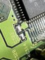
===Logos appear, spin, but BIOS unresponsive - Missing Signals from IC36=== | |||
Electrolytic fluid from C311 can potentially damage the pads for IC36, pins 135-144. Some pins' traces are plainly visible on the top side of the board and should be checked for continuity to IC28. However, Pin 139 is the VSQ signal originating from the CLD-A100, and should connect to Pin D25 of the PAC connector. Pin 140 should have continuity to IC28, pin 30. | |||
<gallery> | |||
PAC-S10 IC36 Fix1.jpg|PAC-S10 IC26 Signals Restored | |||
</gallery> | |||
==Blank Screen on Power Up - Cartridges and BIOS do not load - CSYNC still present== | |||
Assuming no short circuits were measured across any voltage rail on the PAC, one root cause for this issue is the "D15" signal (IC1, Pin 32) being severed. This trace runs directly under C302, which has likely corroded the trace after years of being exposed to electrolytic fluid. | Assuming no short circuits were measured across any voltage rail on the PAC, one root cause for this issue is the "D15" signal (IC1, Pin 32) being severed. This trace runs directly under C302, which has likely corroded the trace after years of being exposed to electrolytic fluid. | ||
| Line 16: | Line 45: | ||
PAC-S10_IC1P32_BadTrace.jpg|D15 Signal from IC1 (68000 CPU) damaged from electrolytic fluid corrosion | PAC-S10_IC1P32_BadTrace.jpg|D15 Signal from IC1 (68000 CPU) damaged from electrolytic fluid corrosion | ||
PAC-S10_IC1P32_Repaired.jpg|D15 Signal from IC1 repaired by connecting to an adjacent via | PAC-S10_IC1P32_Repaired.jpg|D15 Signal from IC1 repaired by connecting to an adjacent via | ||
</gallery> | |||
==No video output at startup (no CSYNC), Works without SSUB attached== | |||
The system reset IC (IC43) has been severed from the reset amplifier for MRES and SRES. Check that IC45, Pin 3 is connected to R66 (bottom side). | |||
<gallery> | |||
PAC-S1 No Video Output Repaired.jpg|IC45, pin 3, restored to Reset Circuit | |||
PAC-S1 SSUB Reset Circuit No Caps.jpg| IC43 Reset Signal runs underneath C422 | |||
</gallery> | </gallery> | ||
Latest revision as of 03:11, 22 November 2023
This page details several faults discovered while servicing various PAC-S10/S1 modules and their solutions.
Partial Troubleshooting Schematic
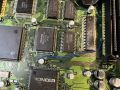
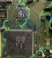
Most times, the Mega Drive/Genesis section of the PAC contains most of the faults that prevent a PAC from working properly. As detailed below, many signals from the 68K and Z80 will become severed from the 315-5660 VDP, leading to a black screen when trying to boot. This schematic has the proper pinout for the 68K CPU package used in the PAC, along with convenient VDP pin references next to each signal to allow users to check continuity from all of the IC's back to the VDP.
PAC-S1/10 MD/Genesis Troubleshooting Schematic
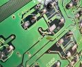
Post-Recap Voltage Rail Check
After performing any capacitor replacement work, it is imperative to check the three voltage rails (+5, +8, -8) for short circuits. If there is a short circuit on any of these rails, it will damage the CLD-A100 player. Both the MAIN and SUB boards have fuses that are labeled with the voltages they protect on the back side of each board. Check that these are not shorted to Ground on BOTH boards. Also note that the SUB board has two grounds - one for digital and one for audio, which are joined together when connected to the MAIN board. The fused 5V rail is referenced to the digital ground and can be checked by measuring continuity to the ground on C506.
Fuse locations on the PAC-S10 MAIN board
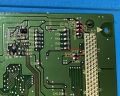
Fuse locations on the PAC-S10 SUB board


Further, after ensuring no shorts, verify that the fuses for the voltage rails still have continuity. If a replacement is needed, a size 0805 1.25A fuse is recommended for the +5V rail and size 0805 0.5A rated fuse for the +8V and -8V rails. These current ratings will ensure that, in the event of a short circuit, the surface mount fuse will blow before the ICP's in the Laseractive.
BIOS Freezes at Power On
This issue has more than one root cause.
No Mega LD/CD Logos appear - PCM ASIC Communication Issue
Missing PCM Chip Select Line
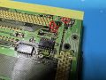
Due to its proximity to C310, electrolytic fluid corrosion could have severed the PCM Chip select line to the SSUB connector, causing a bus collision, as the chip select line on the PCM ASIC has no pulldown/up to counteract a floating state. First, ensure the via to the left of C310 has continuity to IC28, pin 89. Then, check if it has continuity to pin 31 of the SSUB connector. If continuity is missing between either of these, restore it.
PAC-S10, PCM CS signal restored to SSUB connector

Data Line shorted or missing (5V/GND/adjacent pin)
The solder mask on the PAC is easily eaten away by electrolytic fluid. Ensure that the data lines for the PCM ASIC (refer to the schematic) are not shorted to 5V or GND, as the legs of leaded capacitors touching the traces can cause a short.
Additionally, data lines to Program RAM (IC's 24-27) or to the Sub CPU (IC13) may have been eaten by electrolytic fluid. verify all connections (refer to Mega CD 1 schematics).
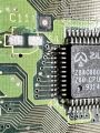
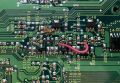
Logos appear, spin, but BIOS unresponsive - Missing Signals from IC36
Electrolytic fluid from C311 can potentially damage the pads for IC36, pins 135-144. Some pins' traces are plainly visible on the top side of the board and should be checked for continuity to IC28. However, Pin 139 is the VSQ signal originating from the CLD-A100, and should connect to Pin D25 of the PAC connector. Pin 140 should have continuity to IC28, pin 30.
PAC-S10 IC26 Signals Restored

Blank Screen on Power Up - Cartridges and BIOS do not load - CSYNC still present
Assuming no short circuits were measured across any voltage rail on the PAC, one root cause for this issue is the "D15" signal (IC1, Pin 32) being severed. This trace runs directly under C302, which has likely corroded the trace after years of being exposed to electrolytic fluid.
Restore the signal by reconnecting Pin 32 to the plated via next to the "40" text, adjacent to the BIOS EEPROM.
D15 Signal from IC1 (68000 CPU) damaged from electrolytic fluid corrosion
D15 Signal from IC1 repaired by connecting to an adjacent via


No video output at startup (no CSYNC), Works without SSUB attached
The system reset IC (IC43) has been severed from the reset amplifier for MRES and SRES. Check that IC45, Pin 3 is connected to R66 (bottom side).
IC45, pin 3, restored to Reset Circuit
IC43 Reset Signal runs underneath C422


Missing/No Sound In Certain Games, Cannot boot Master System games
This is due to a missing data line from the Z80 CPU to the Sega 315-5660 ASIC. C129 is near the lines for D13-15 vias from the Z80 to the 5660 and C111 is near D5-7, increasing the probability of damage from extended exposure to leaked electrolytic fluid. First discover where the signal is lost and then jump the signal to the appropriate trace.
Z80 D14 signal restored to 315-5660 ASIC
Z80 D6 signal restored to 315-5660 ASIC


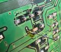
Horizontal Color Smearing
The PAC-S10/S1 employs separate voltage regulators to bias the emitter follower buffers for the RGB signals. The trace that provides voltage to the RED signal buffer is adjacent to C453, which is prone to heavy leakage and can sever the +5V regulated voltage line. This repair can be accomplished by using a thin gauge wire/component lead to jump the top side metal to the bottom side, or a wire can be used to directly jump the signal via the component pads as shown.
Issue caused by RED signal buffer missing a voltage rail
Restoring +5V with a component lead, before trimming
Restoring +5V with a component lead, trimmed
Restoring +5V with a wire


