Master System:SMS II Video Mods: Difference between revisions
VariablePwn (talk | contribs) (Created page) |
Bomb Bloke (talk | contribs) mNo edit summary |
||
| Line 1: | Line 1: | ||
The Sega Master System II has the capacity for Composite and S-Video, but lacks the connections. | [[Master System:Master System Mods Wiki|The Sega Master System II]] has the capacity for Composite and S-Video, but lacks the connections. | ||
The following information taken from [http://raelcunha.com/2016/07/29/my-retro-journey-sega-master-system/ raelgc's blog] highlights the key components required to modify the system to include this. | The following information taken from [http://raelcunha.com/2016/07/29/my-retro-journey-sega-master-system/ raelgc's blog] highlights the key components required to modify the system to include this. | ||
For Composite | ===For Composite=== | ||
Video is taken from Pin 20, and requires a 75 ohm resistor and 220uF capacitor in series, with the positive lead towards the chip, and the negative towards to RCA socket. | Video is taken from Pin 20, and requires a 75 ohm resistor and 220uF capacitor in series, with the positive lead towards the chip, and the negative towards to RCA socket. | ||
| Line 11: | Line 11: | ||
For S-Video | ===For S-Video=== | ||
You will require a standard NPN Transistor and a 27 ohm resistor for the Luma line, and a 75 ohm resistor and 220uF capacitor for Chroma. | You will require a standard NPN Transistor and a 27 ohm resistor for the Luma line, and a 75 ohm resistor and 220uF capacitor for Chroma. | ||
| Line 22: | Line 22: | ||
The following diagram is made by raelgc: | The following diagram is made by raelgc: | ||
[ | [[File:Sms_ii_to_svideo.png]] | ||
[[Category:Master System]] | |||
Revision as of 03:52, 7 April 2024
The Sega Master System II has the capacity for Composite and S-Video, but lacks the connections.
The following information taken from raelgc's blog highlights the key components required to modify the system to include this.
For Composite
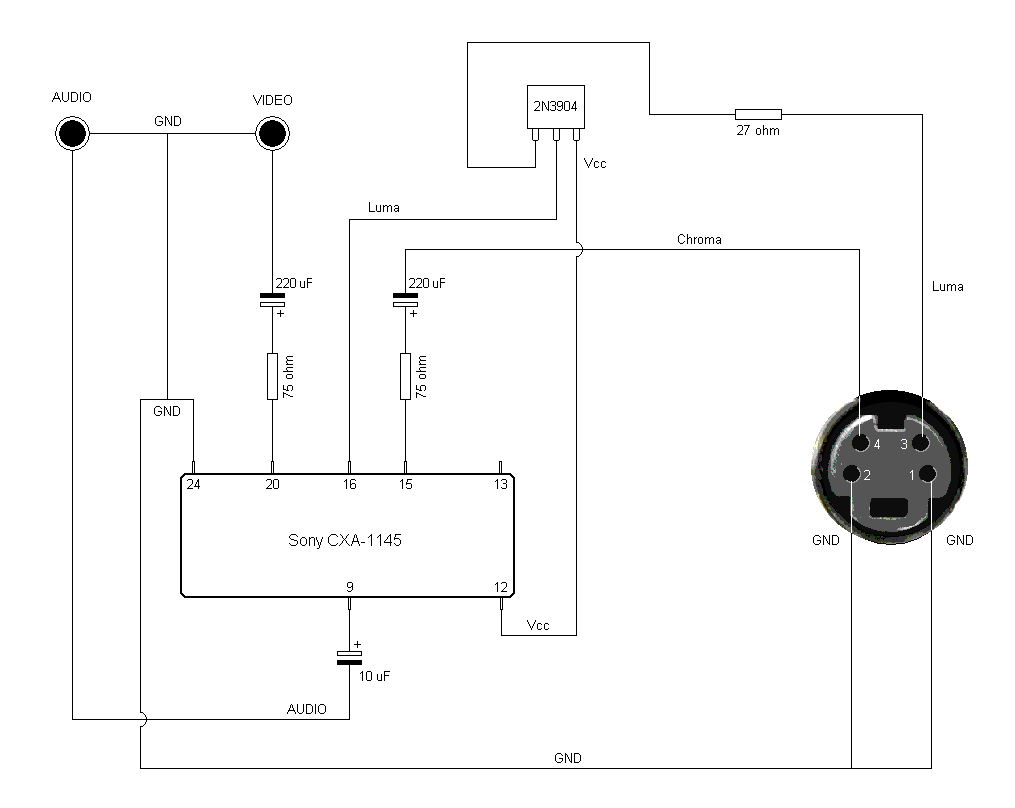
Video is taken from Pin 20, and requires a 75 ohm resistor and 220uF capacitor in series, with the positive lead towards the chip, and the negative towards to RCA socket.
Audio is mono only, and is taken from Pin 9 and requires a 10uF capacitor with the positive lead towards the chip.
For S-Video
You will require a standard NPN Transistor and a 27 ohm resistor for the Luma line, and a 75 ohm resistor and 220uF capacitor for Chroma.
Chroma is located on Pin 15, and requires the resistor and capacitor (positive to chip) in series to the S-Video port (Pin 4, top left).
Luma is a little more tricky, and requires Pin 16 to be connected to the middle pin (Base), the left pin of the transistor (Emitter) is connected to a 27 ohm resistor to the S-Video port (Pin 3, top right). Power for the right leg of the transistor (Collector) can be obtained from Pin 12 of the CXA chip (bottom left).
The following diagram is made by raelgc:
