N64:RGB Mod Basic Amp Install
Jump to navigation
Jump to search
WARNING: Before starting this mod, make sure your N64 can be modded for RGB and that this is the correct mod for your system. If your system is an NTSC N64 with the proper VDC-NUS chip, you can proceed.

RGB Amp
This guide shows RGB mod instructions using a pre-made RGB amp. There are a few different ones available now (some examples shown above), but the installation is similar for all. Any specific differences will be mentioned below.
Voultar's THS7374 amp with built-in sync stripper
Retrofixes THS7314 Amplifier Board
RGB Cable / Sync
= Tools Required =
You'll need a few tools for this mod (more info on the tools can be found in the repair tools section):
- 4.5mm N64 Case Tool
- Philips head screwdriver -
- Soldering iron, solder, and flux
- 26-30 AWG wire
Modding Services
If after reading this guide, you decide you'd rather have a professional do it for you, try these services:
Installation Video
This is a video demonstrating everything shown in this guide.
Installation Procedures
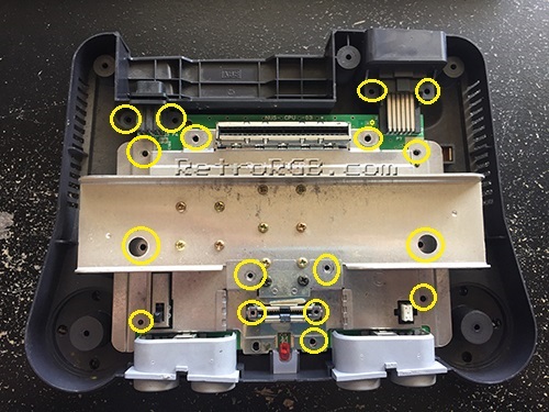
- Remove the memory module, then unbolt the plastic cover using the 4.5mm game tool.
- Unbolt only the screws that are circled in the picture below.
- After removing just those, the entire metal heat shielding will lift off as one piece, exposing the motherboard:
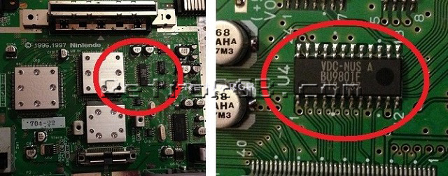
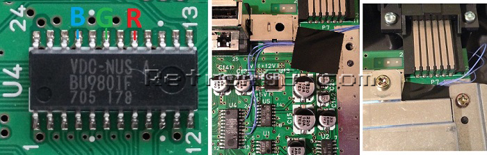
- Once it’s disassembled, look for a chip that says "VDC-NUS" or "VDC-NUS A" (pictured below).
- If you find it, you can proceed with the RGB mod.
- If not, please see the N64 RGB mods page for other options, as your console is not compatible:
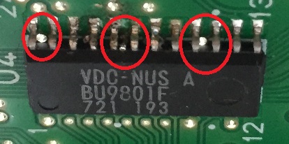
- Flip the motherboard over and look for the RGB vias (holes) labeled R8, R9 and R10.
- Add a bit of flux to each hole, then solder a wire to each.
- R8 = Red
- R9 = Green
- R10 = Blue
- Make sure the stripped wire going through the holes is extremely short!!! If the wire sticks out past the other side of the motherboard, it will actually touch the VDC-NUS chip and possibly hit one of the pins.}}

- Here's an example of what happens if you feed the RGB cables in too far. Luckily this person's N64 wasn't permanently damaged and was able to be fixed, but it was shorting pins together and could have potentially ruined the system:
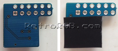
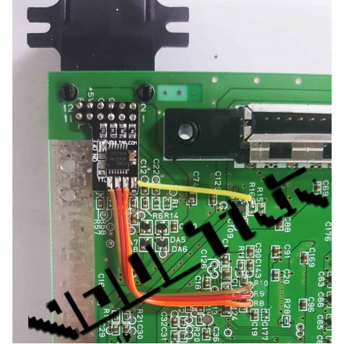
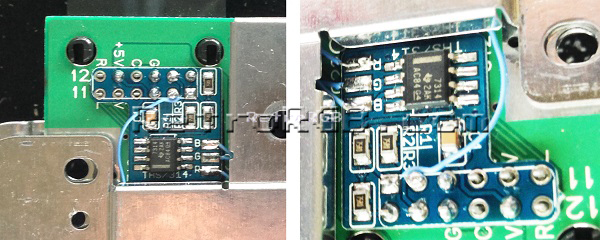
- Next, prepare the pre-made amp by adding a piece of non-conductive tape to the bottom, just to make sure no connections touch the motherboard.
- Slide the amp over the multi-out and solder the pins.
- Run the RGB wires through a bit of heat shrink tubing to keep them neat, then cut them to size and solder them to the RGB board.
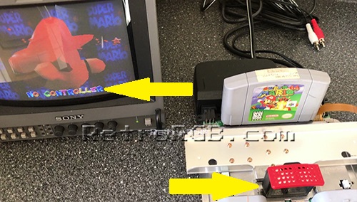
- Test the installation by launching an N64 game. Mario 64 is a good test game, since you can clearly see the red, green and blue colors right at the title screen, both in the letters and on Mario.
- DON'T FORGET - You need to plug the memory module back in, or the N64 won't boot!
- Don't leave the console powered on too long if you have the heatsink off, or you can damage the chips!
- If the installation didn't work properly, it's most likely the connection to the vias:
- Double check that your wires aren't sticking through to the other side of the board. Also, if you didn't use flux, go back and use some...this fixes about 90% of all installation issues.
- As a last resort, you can try soldering directly to the VDC-NUS chip, instead of using the vias. Use pins 17 (Red), 19 (Green) and 21 (Blue). Then, make sure to run the wires cleanly around the board, so that no wires will be pinched when you re-assemble the metal casing. I find this method to be much more of a pain then using the vias, but it will work:


Boards That Support CSYNC
- (not all boards have this option)
If your RGB board deals with sync, then you can enable clean csync output and use a typical SNES csync cable!
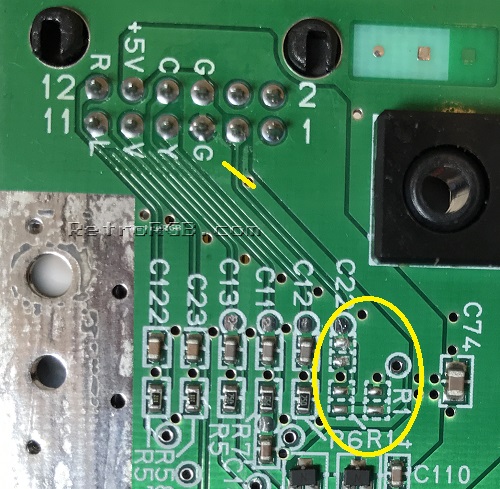
- First and most importantly, make SURE there isn't a signal already traveling to pin 3 (csync) on the multi-out! The easiest and safest way to do this, is simply by removing the three SMD components pictured below that are connected to pin 3:
- Capacitor "C22" / Resistor "R1" / Resistor "R14"
- Alternatively, you can cut the trace on the motherboard, but removing the capacitor is safer, reversible, and debatably easier. Either way, verify the connection has been severed by testing with a multimeter.
- Then, follow the instructions that match your board:
- For boards with a sync stripper circuit, simply short the CSYNC jumper by adding solder to both pads and dragging them together. Once again, verify the connection with a multimeter.
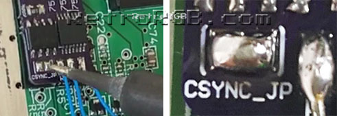
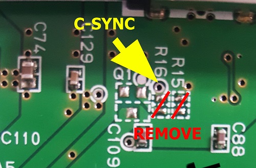
- For boards that process the N64's own sync, you'll need to remove resistors R15 & R16 and solder a wire to the via just above R16, as shown in this picture.
- For boards with a sync stripper circuit, simply short the CSYNC jumper by adding solder to both pads and dragging them together. Once again, verify the connection with a multimeter.


Reassembly / Shielding Mods
- If the installation tested fine, start replacing all the metal shielding (and if any cables are run along the side, make sure they're not getting pinched). If you're using a longer amp board, you'll need to bend the tab on the bottom metal shield, so it doesn't hit the board.
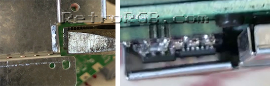
- The smaller pre-made amps should allow just enough space so the metal isn't touching the board and the wires aren't pinched (please ignore the blue wire in the pic, that was from a csync mod). If you wanted to be safe, you could bend the shield as shown above:
- Bolt everything else back in the order you removed it and give it another try. Remember, the memory module has to be plugged in, or the N64 won't boot.
- If you have any trouble, test with a composite video cable to see if the issues occur on composite, or just RGB.

