N64:RGB Mod DIY RGB Amp
Jump to navigation
Jump to search
Ewok
WARNING: Before starting this mod, make sure your N64 can be modded for RGB and that this is the correct mod for your system. If your system is an NTSC N64 with the proper VDC-NUS chip, you can proceed.
Preface
While this mod still works great, the newer pre-made boards tend to be a better choice with more options. You can still use this mod, but if you'd like a pre-made board, click here: N64 Basic RGB Mod - Pre-Made Amp
Tools Required
You'll need a few tools for this mod (more info on the tools can be found in the repair tools section):
- RGB cable
- Soldering skills
- 4.5mm N64 Case Tool
- Philips head screwdriver
- Soldering iron
- Solder (Do not use plumbing solder)
- Thin gauge wire
- (Strongly Recommended) Flux or flux pen
- RGB Amplified Chip, Model # THS7316 - Digikey (US)
- Circuit board to mount the RGB Amp
- 3 x 75 Ohm Resistors, lowest tolerance possible. - Digikey (US) | Mouser(US)
Sync Info:
- Before beginning the RGB mod, you should determine your sync requirements. In almost all cases, simply using an RGB cable that gets sync from luma is the best solution. If your setup requires csync directly from the console, there's more info at the bottom of the N64:cablecsync.
Installation Procedures
- **Please note:** All pictures in this guide show the THS7314 amp, but I actually recommend you use the 7316 (installation is identical). The [thsamps.html THS Amp Page] will give you detailed information as to why, as well instructions on how to build the circuit.
- \- Start by [thsamps.html assembling the RGB amp circuit]. Also, here's a trick: After you cut the excess pins from the resistors, **_save them_** for later in this guide!!!
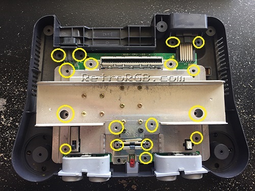
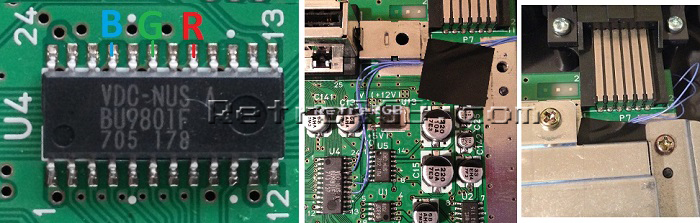
- \- Next, remove the memory module, then unbolt the plastic cover using the 4.5mm game tool. Then, unbolt only the screws that are circled in the picture below. After removing just those, the entire metal heat shielding will lift off as one piece, exposing the motherboard:
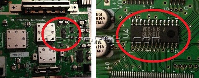
- \- Once it’s disassembled, look for a chip that says "VDC-NUS" or "VDC-NUS A" (pictured below). If you find it, you can proceed with the RGB mod. If not, please see the [n64rgbcompatible.html N64 RGB mods page] for other options, as your console is not compatible:
- Flip the motherboard over and look for the RGB via's (holes) labeled R8, R9 and R10. Add a bit of flux to each hole, then solder a wire to each. If you'd like to try a cleaner way to install this board, use the excess that you cut off from the resistors and mount the amp directly to the N64's via, like shown in the [snesminidiybypass.html SNES Mini DIY Bypass instructions].
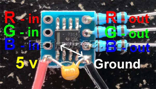
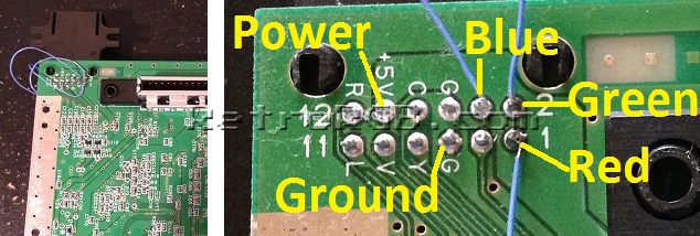
- Here's the pinout:
- R8 = Red R9 = Green R10 = Blue
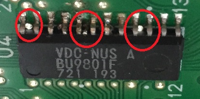
- **Warning**: Make sure the stripped wire going through the holes is _extremely_ short!!! If the wire sticks out past the other side of the motherboard, it will actually touch the VDC-NUS chip and possibly hit one of the pins!:

- > Here's an example of what happens if you feed the RGB cables in too far. Luckily this person's N64 wasn't permanently damaged and I was able to fix it, but it was shorting pins together and could have potentially ruined the system:
- >
- \- Then, find the multi-out on the bottom of the motherboard and solder the red, green and blue connections from the amplifier board to the multi-out port on the motherboard, as well as "+5V" and ground, "G":
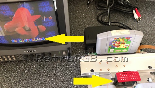
- \- Next, test the installation by launching an N64 game. I like using Mario 64, since you can clearly see the red, green and blue colors right at the title screen, both in the letters and on Mario. DON'T FORGET - You need to plug the memory module back in, or the N64 won't boot! A few times I forgot and thought I may have done the mod wrong. Also, don't leave it powered on too long if you have the heatsink off, or you can damage the chips:
- \- If the installation didn't work properly, it's most likely the connection to the via's:
- > Double check that your wires aren't sticking through to the other side of the board. Also, if you didn't use flux, go back and use some...this fixes about 90% of all installation issues.
- >
- > As a last resort, you can try soldering directly to the VDC-NUS chip, instead of using the via's. Use pins 17 (Red), 19 (Green) and 21 (Blue). Then, make sure to run the wires cleanly around the board, so that no wires will be pinched when you re-assemble the metal casing. I find this method to be much more of a pain then using the via's, but it will work:
- >


- Reassembly / Shielding Mods:**
- \- Start replacing all the metal shielding and make sure the cables are not getting pinched. If you ran the wires around the side, make sure they're out of the way of the metal shielding when you re-assemble the case.
- \- Lastly, bolt everything back in the order you removed it and give it a try. Remember, the memory module has to be plugged in, or the N64 won't boot.
- Some quick tips:**
- \- If you have any trouble, test with a composite video cable to see if the issues occur on composite, or just RGB.
- \- I've seen people just connect the RGB pins to the multi-out with no amp. While technically it would work on some RGB monitors, it will most likely damage your console. Definitely don't try it! Here's an example comparing with and without the amp:
- [[[File:N64%20Cable%20Compare%2001%20-%20Small.jpg)](https://cdn.retrorgb.com/images/N64%20Cable%20Compare%20-%2001.jpg]]
Well, that's it! Feel free to go back to [/n64.html the main N64 page]. If you'd like info on mods for other systems, head to the [/systems.html Getting RGB From Each System page] or check out [/ the main page] for more retro-awesomeness.