NES:Famicom Disk System Glitching Sprites Fix: Difference between revisions
Jump to navigation
Jump to search
No edit summary |
mNo edit summary |
||
| Line 1: | Line 1: | ||
Certain combinations of Famicom and Famicom Disk System (FDS) RAM adapter units have an issue which causes sprites to appear glitchy due to interference on the FDS RAM cart pins. The issue seems to affect mostly Famicoms made in 1989 and RAM adapters with boards marked "HVC-FMR-03" and some early "HVC-FMR-02" boards. Information for this guide was compiled from multiple sources.<ref>https://retro.supermegabyte.com/2018/07/23/fix-glitchy-famicom-disk-system-sprites/</ref><ref>https://www.famicomworld.com/forum/index.php?topic=10607.0</ref><ref>https://synt4x.org/blog/index.php/2018/01/19/glitchy-graphics-on-famicom-disk-system/</ref><ref>https://twitter.com/SuperZvesda/status/1639694888944951297</ref> | Certain combinations of Famicom and Famicom Disk System (FDS) RAM adapter units have an issue which causes sprites to appear glitchy due to interference on the FDS RAM cart pins. The issue seems to affect mostly Famicoms made in 1989 and RAM adapters with boards marked "HVC-FMR-03" and some early "HVC-FMR-02" boards. Information for this guide was compiled from multiple sources.<ref>https://retro.supermegabyte.com/2018/07/23/fix-glitchy-famicom-disk-system-sprites/</ref><ref>https://www.famicomworld.com/forum/index.php?topic=10607.0</ref><ref>https://synt4x.org/blog/index.php/2018/01/19/glitchy-graphics-on-famicom-disk-system/</ref><ref>https://twitter.com/SuperZvesda/status/1639694888944951297</ref> | ||
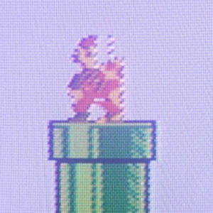
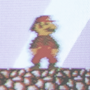
<div class="inline-thumb">[[File:FDS Glitching Sprites Before.png|thumb|Sprite issue affecting Mario.]] [[File:FDS Glitching Sprites After.png|thumb|After sprite issue fix.]]</div> | <div class="inline-thumb">[[File:FDS Glitching Sprites Before.png|thumb|Sprite issue affecting Mario.<br>Credit to Shane from [https://retro.supermegabyte.com/2018/07/23/fix-glitchy-famicom-disk-system-sprites/ SuperMegaByte].]] [[File:FDS Glitching Sprites After.png|thumb|After sprite issue fix.<br>Credit to Shane from [https://retro.supermegabyte.com/2018/07/23/fix-glitchy-famicom-disk-system-sprites/ SuperMegaByte].]]</div> | ||
{{br}} | {{br}} | ||
| Line 11: | Line 11: | ||
#* Alternatively, you can use eight 4.7kohm resistors and solder one end together. | #* Alternatively, you can use eight 4.7kohm resistors and solder one end together. | ||
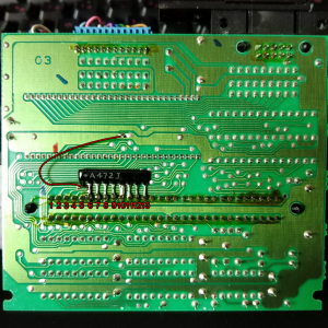
# Use electrical tape to line up the resistor array as shown below and hold it in place. | # Use electrical tape to line up the resistor array as shown below and hold it in place. | ||
#: [[File:FDS Glitching Sprites Fix.png| | #: <div class="inline-thumb">[[File:FDS Glitching Sprites Fix.png|thumb|Credit to Shane from [https://retro.supermegabyte.com/2018/07/23/fix-glitchy-famicom-disk-system-sprites/ SuperMegaByte].]]</div>{{br}} | ||
# Bend the first pin of the resistor array upwards so that it doesn't make contact with anything on the board. | # Bend the first pin of the resistor array upwards so that it doesn't make contact with anything on the board. | ||
# Solder a wire between the first pin and ground. Example ground point shown in image above. | # Solder a wire between the first pin and ground. Example ground point shown in image above. | ||
Revision as of 16:03, 26 March 2023
Certain combinations of Famicom and Famicom Disk System (FDS) RAM adapter units have an issue which causes sprites to appear glitchy due to interference on the FDS RAM cart pins. The issue seems to affect mostly Famicoms made in 1989 and RAM adapters with boards marked "HVC-FMR-03" and some early "HVC-FMR-02" boards. Information for this guide was compiled from multiple sources.[1][2][3][4]
Solution
The solution is to add resistors on the data pins of the FDS RAM cart unit, which fixes the interference.
- Obtain a 9-pin 4.7kohm resistor array.
- Alternatively, you can use eight 4.7kohm resistors and solder one end together.
- Use electrical tape to line up the resistor array as shown below and hold it in place.
 Credit to Shane from SuperMegaByte.
- Bend the first pin of the resistor array upwards so that it doesn't make contact with anything on the board.
- Solder a wire between the first pin and ground. Example ground point shown in image above.
- Solder pin 2 of the resistor array to pin 6 of the FDS RAM adapter.
- Solder the remaining pins of the resistor array to the FDS RAM adapter pins. Pins 6-13 should all be connected to the resistor array.