(2 intermediate revisions by the same user not shown)
Line 1:
Line 1:
[[File:RGB2C02N.png|thumb|The RGB2C02N]]
The [https://www.kadenken.com/view/item/000000001707 RGB2C02N] is a mod that replaces the PPU and offers RGB output as well as a changing the clock speed of the PPU from 15KHz to 31KHz, which increases the sprite limit per line from 8 to 15 (known as "SPEX mode"). This removes nearly all sprite flicker from NES and Famicom games.
The [https://www.kadenken.com/view/item/000000001707 RGB2C02N] is a mod that replaces the PPU and offers RGB output as well as a changing the clock speed of the PPU from 15KHz to 31KHz, which increases the sprite limit per line from 8 to 15 (known as "SPEX mode"). This removes nearly all sprite flicker from NES and Famicom games.
Line 16:
Line 17:
== Installation ==
== Installation ==
An installation video is available on [https://www.youtube.com/watch?v=Kw1bP3eQU5Y Scruffy Lookin RGB's YouTube channel]. Note that this video and this text guide apply to model HVCN-CPU-01 units. If you have another model, it will likely have different motherboard pinouts (except the AV multi-out port).
=== Required Materials ===
=== Required Materials ===
Latest revision as of 21:27, 12 April 2024
The RGB2C02N
The RGB2C02N is a mod that replaces the PPU and offers RGB output as well as a changing the clock speed of the PPU from 15KHz to 31KHz, which increases the sprite limit per line from 8 to 15 (known as "SPEX mode"). This removes nearly all sprite flicker from NES and Famicom games.
Note that this mod does not support YPbPr, s-video, or composite and only supports NTSC output.
An installation video is available on Scruffy Lookin RGB's YouTube channel. Note that this video and this text guide apply to model HVCN-CPU-01 units. If you have another model, it will likely have different motherboard pinouts (except the AV multi-out port).
Required Materials
Phillips head screwdriver
4.5 mm gamebit screwdriver (required for NES top loader and AV Famicom)
Soldering iron, solder, flux, wire, and wire stripper
Desoldering gun (not required, but highly recommended as it makes removing the PPU much easier)
RGB2C02N
Assemble the RGB2C02N PCB.
Disassemble the console and fully remove the motherboard from the shell.
If you have a SN74LS373N chip, replace it with a SN74HC373N chip.
Desolder the PPU (the chip with the markings starting with RP2C02) and clean the motherboard with isopropyl alcohol.
Desolder capacitor C5 and lay it flat, giving more space around the PPU area.
Lift one leg of resistor R6 to effectively disconnect that trace.
Solder the DIP socket in place, matching the dimple of the socket to the dimple indicated on the silkscreen of the motherboard.
Insert the short end of the pin headers into the bottom side of the RGB2C02N board and then insert the second socket on top of it before soldering it into place. Inserting the socket before soldering will ensure the headers are installed in the correct position.
Insert the EEPROM into the RGB2C02N.
Insert the RGB2C02N into the socket on the motherboard.
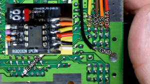
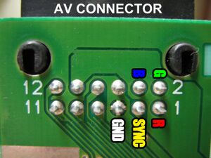
Add fresh solder to the Multiout pins and solder wires from the R, G, B, Sync, and Ground pins to the respective labelled pads on the RGB2C02N.
Assemble the 1PCON PCB. Verify correct orientation of the diode with a multimeter with the right side being the negative side.
Solder wires from the COL1, COL0, SPEX, and MODE pads on the 1PCON PCB to the RGB2C02N.
Solder wires from the CLK, VCC, P/S, DATA, EXT-13, and GND pins on the motherboard to the 1PCON.
Optionally, solder long wires to the LED pins and mount an LED somewhere in the case, such as near the back vent. This LED is active when SPEX mode is enabled.
Usage
Hold Select + A + Down to turn on SPEX mode, which will toggle between the default (15KHz) and increased (31KHz) PPU speeds.
Hold Select + B + Up to change your color palette between one of three options. More palettes are available if you program the EEPROM.