|
|
| Line 1: |
Line 1: |
| [[Category:RetroRGB Migration]] | | [[Category:RetroRGB Migration WIP]] Mitch1256 |
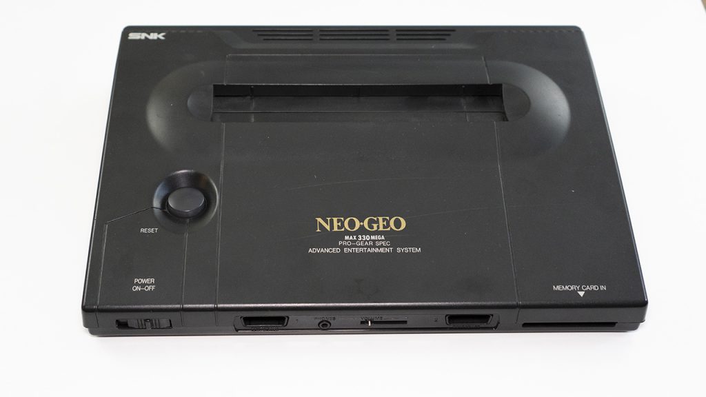
| | This page will show you a "basic" bypass for the Neo Geo AES console that eliminates the Sony CXA amp and sends video (at the proper voltage) directly from the NG's digital-to-analog-converter, to the multi-out. This was tested on the worst revision Neo-Geo, the 3-6, however it should work on other revisions. |
|
| |
|
| This page will show you a "basic" bypass for the Neo Geo AES console that eliminates the Sony CXA amp and sends video (at the proper voltage) directly from the NG's digital-to-analog-converter, to the multi-out. This was tested on the worst revision Neo-Geo, the 3-6, however it should work on other revisions. A shoutout to [https://twitter.com/mmmonkey mmmonkey], as this guide stemmed from [http://www.mmmonkey.co.uk/snk-neo-geo-aes-rgb-bypass/ Pete's original work]. A second shoutout to Alex, as [https://www.arcade-projects.com/forums/index.php?thread/176-neo-geo-aes-rgb-bypass-with-ths7314-rgb-amp/ his original RGB bypass] will pave the way for future, even better mods. | | WARNING: This mod will disable composite video! |
|
| |
|
| **WARNING:** This mod will disable composite video!
| | [[File:NeoGeoAES3-6-1024x576.jpg]] |
|
| |
|
| [[[File:NeoGeoAES3-6-1024x576.jpg)](https://cdn.retrorgb.com/wp-content/uploads/2019/03/NeoGeoAES3-6.jpg]]
| | It's been long discussed that some Neo Geo's output better RGB video than others. While that's true, all AES' can have a fairly simple RGB bypass performed that gets the best out of the built-in DAC. That means you can make every revision AES look identical, regardless of serial number, including and especially the notorious 3-6 revision motherboard. |
|
| |
|
| It's been long discussed that some Neo Geo's output better RGB video than others. While that's true, all AES' can have a fairly simple RGB bypass performed that gets the best out of the built-in DAC. That means you can make _every_ revision AES look identical, regardless of serial number, including and especially the notorious 3-6 revision motherboard.
| | ==== Tools Needed: ==== |
| | |
| In fact, it's my opinion that people with 3-6's should consider this mod essential, as the stock output is absolutely terrible! Lets get started...
| |
| | |
| ==== **Tools Needed:** ==== | |
|
| |
|
| * Basic soldering skills | | * Basic soldering skills |
| Line 20: |
Line 17: |
| Access full-sized pictures in this guide, simply by clicking each one! | | Access full-sized pictures in this guide, simply by clicking each one! |
|
| |
|
| ==== **Disassembly** ==== | | ==== Disassembly ==== |
| | |
| Start by removing the two screws on the bottom of the AES. Please note that these are different sizes, so make sure to mark where each goes! Also, carefully try to lift the three footpads marked here to expose the other screws; There's no screw under the unmarked 4th pad. [[[File:NeoGeoAES3-6_Bottom-300x169.jpg)](https://cdn.retrorgb.com/wp-content/uploads/2019/03/NeoGeoAES3-6_Bottom.jpg]]
| |
| | |
| Unfortunately, due to the age of these footpads, they'll most likely break. If you get lucky, you can peel them back just enough to get your screwdriver in, but expect to accidentally break at least one: [[[File:NeoGeoAES3-6_Footpads-300x129.jpg)](https://cdn.retrorgb.com/wp-content/uploads/2019/03/NeoGeoAES3-6_Footpads.jpg]]
| |
| | |
| After removing the top plastic cover, remove the following screws. Once done, remove the reset button and power switch, then carefully lift the motherboard out of the bottom case. [[[File:NeoGeoAES3-6_MotherboardScrews-1024x767.jpg)](https://cdn.retrorgb.com/wp-content/uploads/2019/03/NeoGeoAES3-6_MotherboardScrews.jpg]]
| |
| | |
|
| |
| | |
| ==== **RGB Bypass** ====
| |
| | |
| Now you'll need to remove six components located in the top-left of the motherboard, next to the A/V out port: Three resistors and three capacitors. The ideal way to remove them is with a desoldering gun, however if you're careful, you can use a soldering iron and some tweezers, or even snip them out with cutters (please be careful with cutters!): [https://cdn.retrorgb.com/wp-content/uploads/2019/03/NeoGeoAES3-6_TopMotherboard.jpg [[File:NeoGeoAES3-6_TopMotherboard-1024x787.jpg)] [images/NeoGeoAES3-6_RemoveRGBcomponents-1024x817.jpg ![]](https://cdn.retrorgb.com/wp-content/uploads/2019/03/NeoGeoAES3-6_RemoveRGBcomponents.jpg]]
| |
| | |
| That area should now look like this: [[[File:NeoGeoAES3-6_RemovedRGBcomponents-1024x737.jpg)](https://cdn.retrorgb.com/wp-content/uploads/2019/03/NeoGeoAES3-6_RemovedRGBcomponents.jpg]]
| |
| | |
| Now, flip the motherboard over and locate the area near the A/V Multi-out; The upper right of this picture: [[[File:NeoGeoAES3-6_MotherboardBottom-1024x748.jpg)](https://cdn.retrorgb.com/wp-content/uploads/2019/03/NeoGeoAES3-6_MotherboardBottom.jpg]]
| |
| | |
| You'll need to connect each of the following points with a 150Ohm resistor (technique, tips & more explanation below): [[[File:NeoGeoAES3-6_RGBpointsBefore-1024x801.jpg)](https://cdn.retrorgb.com/wp-content/uploads/2019/03/NeoGeoAES3-6_RGBpointsBefore.jpg]]
| |
| | |
| I like to use the resistor itself to make the connection, with no wire: I trim one end of the resistor and solder it to the bottom pins. Then I measure and position the resistor with the connection points on the multi-out (top pins) and trim to size. I start with #1 in the above picture, as that's the only one that needs a bend in the routing; The rest are strait shots, so I do the hardest first. Next I add the heatshrink tubing. Then I solder the top connection in place. Lastly, I add some heat to shrink the tubing down for a nice connection. [[[File:NeoGeoAES3-6_RGBpointsAfter-1024x740.jpg)](https://cdn.retrorgb.com/wp-content/uploads/2019/03/NeoGeoAES3-6_RGBpointsAfter.jpg]]
| |
| | |
|
| |
| | |
| ==== **Sync Isolation** ====
| |
| | |
| **Important note: ** This mod may not be needed at all on other revision AES consoles. Technically, this isn't "needed" on the 3-6's either, but I strongly recommend doing it. You'll get a cleaner signal at a better voltage (more on that below) and since you lose composite video anyway, you'd might as well get the best you can for just a few more easy steps!
| |
| | |
| Start by connecting a wire to the bottom of pin 11 (csync-out) of the Sony CXA. Then, run that wire through one of the existing holes of a capacitor you previously removed. DO NOT SOLDER TO THE HOLE!!! Simply push the wire through to the other side! Note that I've routed this wire away from other pins and components: [[[File:NeoGeoAES3-6_CXAsync-1024x596.jpg)](https://cdn.retrorgb.com/wp-content/uploads/2019/03/NeoGeoAES3-6_CXAsync.jpg]]
| |
| | |
| Next, carefully snip the positive input leg of the following capacitor and carefully rotate it. If you have a desoldering iron, it would be _much_ better to desolder the whole cap, rotate it and solder the negative side back in place: [[[File:NeoGeoAES3-6_CompositeVideoCap-1024x599.jpg)](https://cdn.retrorgb.com/wp-content/uploads/2019/03/NeoGeoAES3-6_CompositeVideoCap.jpg]]
| |
| | |
| Lastly, solder the wire that you ran through the hole, to the positive input side of the capacitor you just rotated. Then snip any excess. [[[File:NeoGeoAES3-6_CompositeVideoCapCsync-1024x635.jpg)](https://cdn.retrorgb.com/wp-content/uploads/2019/03/NeoGeoAES3-6_CompositeVideoCapCsync.jpg]]
| |
| | |
|
| |
|
| |
|
| ==== **Quality Improvement:** ====
| | Start by removing the two screws on the bottom of the AES. Please note that these are different sizes, so make sure to mark where each goes! Also, carefully try to lift the three footpads marked here to expose the other screws; There's no screw under the unmarked 4th pad. [[File:NeoGeoAES3-6_Bottom-300x169.jpg]] |
|
| |
|
| Here's a video demonstrating the before and after of what this mod looks like on a 3-6 AES. Keep in mind the "before" won't be as bad on most other revision AES consoles, but the "after" is an accurate representation of what to expect:
| | Unfortunately, due to the age of these footpads, they'll most likely break. If you get lucky, you can peel them back just enough to get your screwdriver in, but expect to accidentally break at least one: [[File:NeoGeoAES3-6_Footpads-300x129.jpg]] |
|
| |
|
| https://youtu.be/0ysA7U4BYXs
| | After removing the top plastic cover, remove the following screws. Once done, remove the reset button and power switch, then carefully lift the motherboard out of the bottom case. [[File:NeoGeoAES3-6_MotherboardScrews-1024x767.jpg]] |
|
| |
|
| | | |
|
| |
|
| ==== **Oscilloscope Analysis** ==== | | ==== RGB Bypass ==== |
|
| |
|
| Let's take a look at the results of this mod from an electrical standpoint. Keep in mind that every console will always have a certain percentage difference in tolerance levels; Unless you replace every single component on the board with 0.1% versions, expect at least a 5% difference in readings.
| | Now you'll need to remove six components located in the top-left of the motherboard, next to the A/V out port: Three resistors and three capacitors. The ideal way to remove them is with a desoldering gun, however if you're careful, you can use a soldering iron and some tweezers, or even snip them out with cutters (please be careful with cutters!): [[File:NeoGeoAES3-6_TopMotherboard-1024x787.jpg]] [[NeoGeoAES3-6_RemoveRGBcomponents.jpg]] |
|
| |
|
| For this particular console, we see a reading of 760mV on the color lines of the unmodified console (RGB were all the same value, so I'll just show red). Anything over 714mV has the potential to wash out the colors, so this is bad from the start. After the bypass, we see the level drop to a much better 708mV and I've seen 3-6 AES' as low as 670mV after performing this mod - A bit too low is much better than the high values of the original output. [[[File:NeoGeoAES3-6_BypassScopeRed-1024x307.jpg)](https://cdn.retrorgb.com/wp-content/uploads/2019/03/NeoGeoAES3-6_BypassScopeRed.jpg]]
| | That area should now look like this: [[File:NeoGeoAES3-6_RemovedRGBcomponents-1024x737.jpg]] |
|
| |
|
| Also, notice the signal itself: You can see the much "cleaner" signal on the output side, represented by the straighter line!
| | Now, flip the motherboard over and locate the area near the A/V Multi-out; The upper right of this picture: [[File:NeoGeoAES3-6_MotherboardBottom-1024x748.jpg]] |
|
| |
|
| Next, lets' take a look at sync. Before performing the mod, you actually get full composite video on both the "csync" and "cvbs" pins, as they're oddly connected on the motherboard: [https://cdn.retrorgb.com/wp-content/uploads/2019/03/NeoGeoAES3-6_ScopeCVBS.jpg [[File:NeoGeoAES3-6_ScopeCVBS.jpg)] [images/NeoGeoAES3-6_CVBSandCSYNCconnect-1024x562.jpg ![]](https://cdn.retrorgb.com/wp-content/uploads/2019/03/NeoGeoAES3-6_CVBSandCSYNCconnect.jpg]]
| | You'll need to connect each of the following points with a 150Ohm resistor (technique, tips & more explanation below): [[File:NeoGeoAES3-6_RGBpointsBefore-1024x801.jpg]] |
|
| |
|
| After the initial RGB mod (but before the csync mod), you’ll lose most of the composite video signal, but there’s still some excess noise corrupting the remaining sync waveform. Also, while this voltage is perfectly fine, some hobbyist-built retro-gaming devices work more reliably with a slightly higher sync voltage. [[[File:NeoGeoAES3-6_ScopeCVBSafterMod.jpg)](https://cdn.retrorgb.com/wp-content/uploads/2019/03/NeoGeoAES3-6_ScopeCVBSafterMod.jpg]]
| | Use the resistor itself to make the connection, with no wire: trim one end of the resistor and solder it to the bottom pins. Then measure and position the resistor with the connection points on the multi-out (top pins) and trim to size. Start with #1 in the above picture, as that's the only one that needs a bend in the routing; The rest are strait shots. Next add the heatshrink tubing. Then solder the top connection in place. Lastly, add some heat to shrink the tubing down for a nice connection. [[File:NeoGeoAES3-6_RGBpointsAfter-1024x740.jpg]] |
| | |
| Here's the same signal after the csync mod: One picture to show voltage and the other with the measurement bars off so you can get a good look at the signal itself. You can see the voltage is now at 366mV and it's a much cleaner signal. This is probably going to help more with compatibility and not so much picture quality, but in my opinion it's so easy you'd might as well just do it: [[[File:NeoGeoAES3-6_ScopeCsyncMod-1024x307.jpg)](https://cdn.retrorgb.com/wp-content/uploads/2019/03/NeoGeoAES3-6_ScopeCsyncMod.jpg]]
| |
|
| |
|
| | | |
|
| |
|
| ==== **Final Thoughts** ==== | | ==== Sync Isolation ==== |
|
| |
|
| While I'm sure some revisions of the AES output RGB quality that's good enough for many people, if your AES is plagued with the same interference and "jailbars" as the one shown in this guide, you should really perform this easy mod. In my opinion, loosing composite video is a small price to pay for such a giant upgrade in quality. Here's another example of the difference it makes, via before and after shots of SMPTE color bars, scaled nearest-neighbor to 5x: [[[File:NeoGeoAES3-6_BaAcolorbars-1024x384.png)](https://cdn.retrorgb.com/wp-content/uploads/2019/03/NeoGeoAES3-6_BaAcolorbars.png]]
| | Important note: This mod may not be needed at all on other revision AES consoles. Technically, this isn't "needed" on the 3-6's either, but it's strongly recommended to do it. You'll get a cleaner signal at a better voltage. |
|
| |
|
| Overall, if you have a 3-6, this should be a mod you seriously consider!
| | Start by connecting a wire to the bottom of pin 11 (csync-out) of the Sony CXA. Then, run that wire through one of the existing holes of a capacitor you previously removed. DO NOT SOLDER TO THE HOLE!!! Simply push the wire through to the other side! [[File:NeoGeoAES3-6_CXAsync-1024x596.jpg]] |
|
| |
|
| | | Next, carefully snip the positive input leg of the following capacitor and carefully rotate it. If you have a desoldering iron, it would be much better to desolder the whole cap, rotate it and solder the negative side back in place: [[File:NeoGeoAES3-6_CompositeVideoCap-1024x599.jpg]] |
|
| |
|
| That's it for now! Feel free to go back to [https://www.retrorgb.com/neogeo.html the main Neo Geo section], or head to [https://www.retrorgb.com the main page] to be kept in the loop with everything going on in the retro-gaming scene!
| | Lastly, solder the wire that you ran through the hole, to the positive input side of the capacitor you just rotated. Then snip any excess. [[File:NeoGeoAES3-6_CompositeVideoCapCsync-1024x635.jpg]] |
Mitch1256
This page will show you a "basic" bypass for the Neo Geo AES console that eliminates the Sony CXA amp and sends video (at the proper voltage) directly from the NG's digital-to-analog-converter, to the multi-out. This was tested on the worst revision Neo-Geo, the 3-6, however it should work on other revisions.
WARNING: This mod will disable composite video!
It's been long discussed that some Neo Geo's output better RGB video than others. While that's true, all AES' can have a fairly simple RGB bypass performed that gets the best out of the built-in DAC. That means you can make every revision AES look identical, regardless of serial number, including and especially the notorious 3-6 revision motherboard.
Tools Needed:
- Basic soldering skills
- Soldering iron, wire, heatshrink tubing
- 150 Ohm resistors
- Desoldering gun not necessary, but might make it easier
Access full-sized pictures in this guide, simply by clicking each one!
Disassembly
Start by removing the two screws on the bottom of the AES. Please note that these are different sizes, so make sure to mark where each goes! Also, carefully try to lift the three footpads marked here to expose the other screws; There's no screw under the unmarked 4th pad. 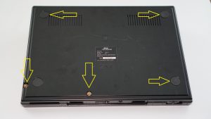
Unfortunately, due to the age of these footpads, they'll most likely break. If you get lucky, you can peel them back just enough to get your screwdriver in, but expect to accidentally break at least one: 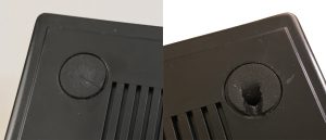
After removing the top plastic cover, remove the following screws. Once done, remove the reset button and power switch, then carefully lift the motherboard out of the bottom case. 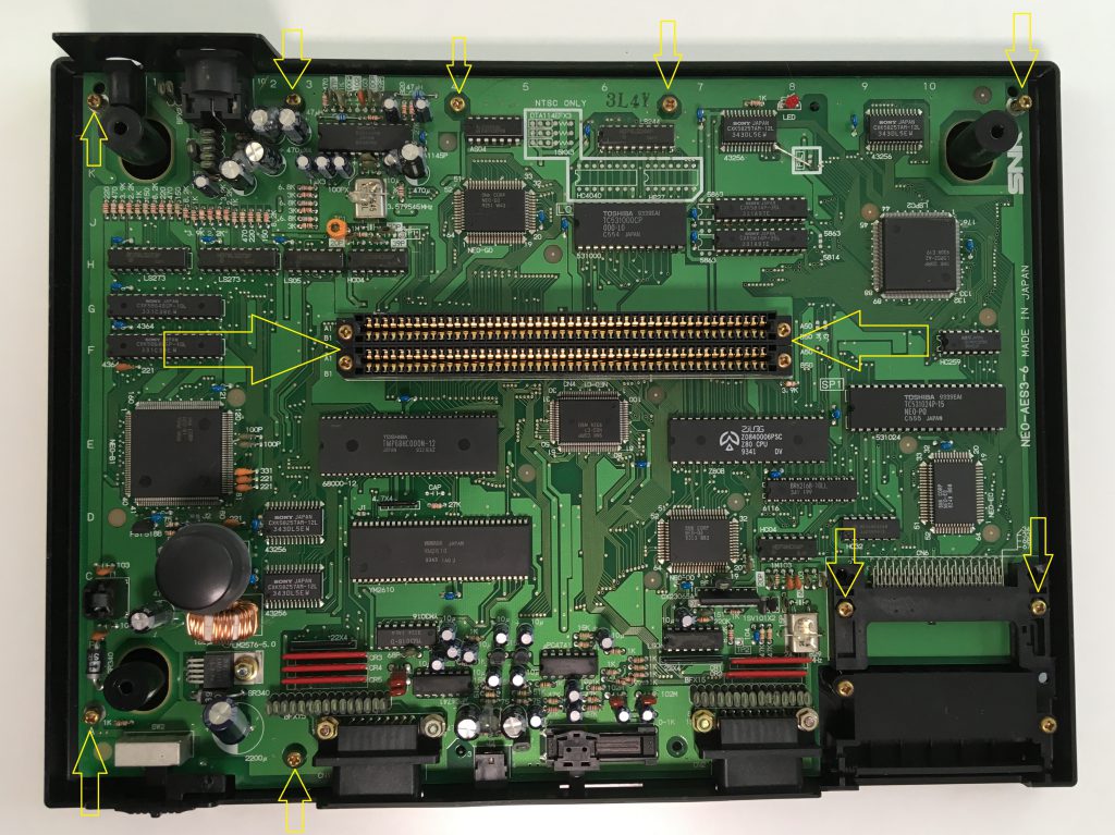
RGB Bypass
Now you'll need to remove six components located in the top-left of the motherboard, next to the A/V out port: Three resistors and three capacitors. The ideal way to remove them is with a desoldering gun, however if you're careful, you can use a soldering iron and some tweezers, or even snip them out with cutters (please be careful with cutters!): 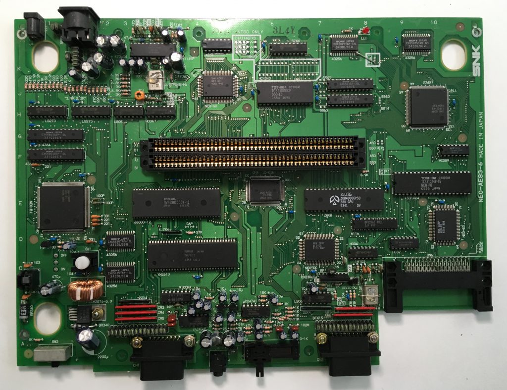 NeoGeoAES3-6_RemoveRGBcomponents.jpg
That area should now look like this: 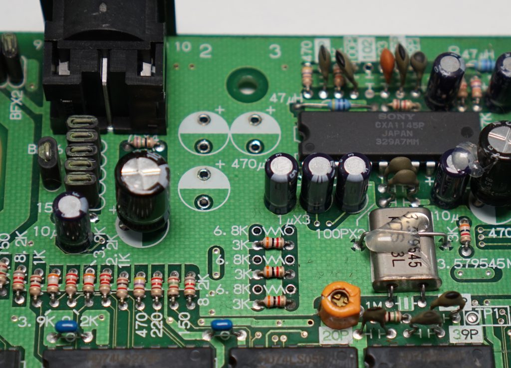
Now, flip the motherboard over and locate the area near the A/V Multi-out; The upper right of this picture: 
You'll need to connect each of the following points with a 150Ohm resistor (technique, tips & more explanation below): 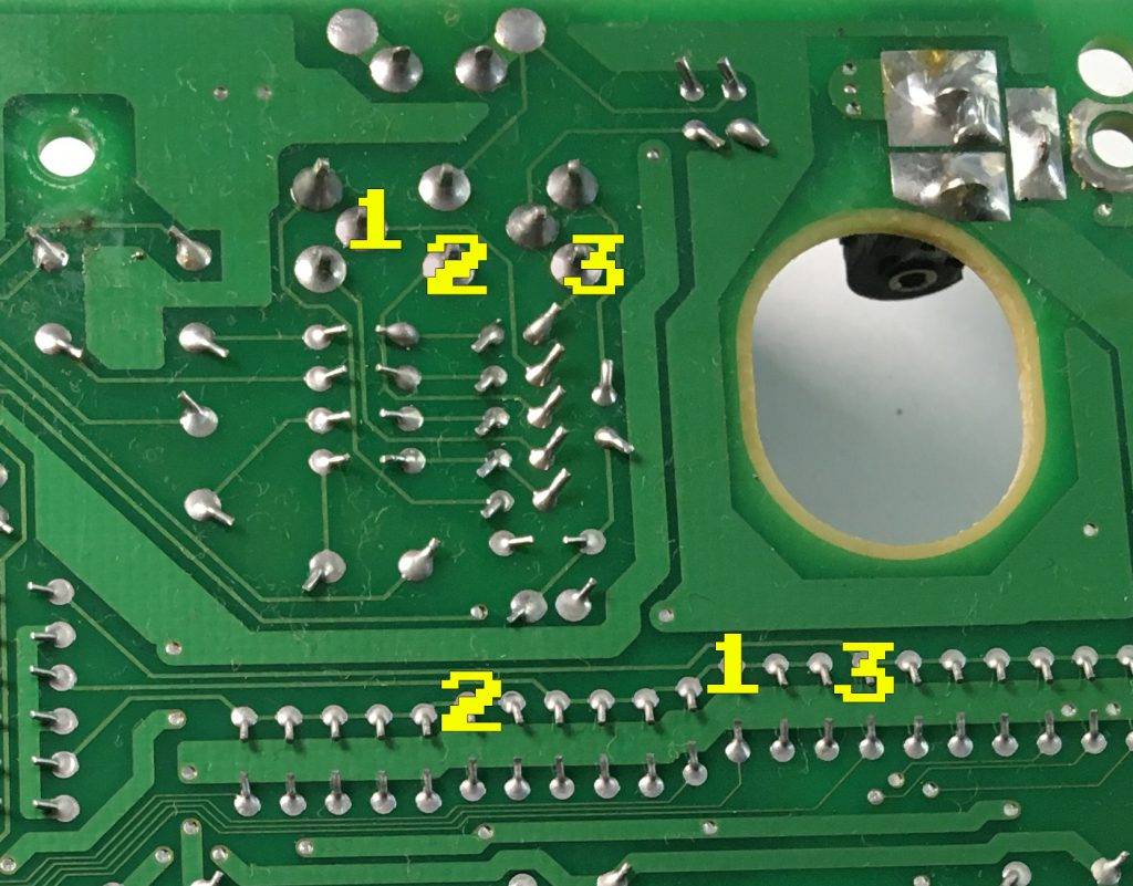
Use the resistor itself to make the connection, with no wire: trim one end of the resistor and solder it to the bottom pins. Then measure and position the resistor with the connection points on the multi-out (top pins) and trim to size. Start with #1 in the above picture, as that's the only one that needs a bend in the routing; The rest are strait shots. Next add the heatshrink tubing. Then solder the top connection in place. Lastly, add some heat to shrink the tubing down for a nice connection. 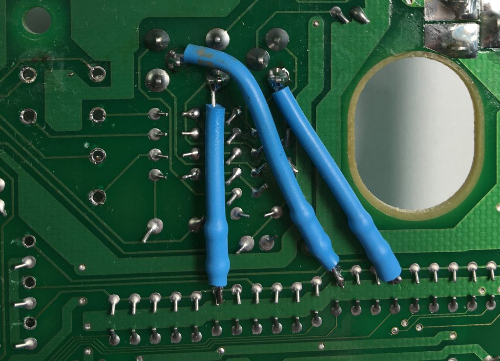
Sync Isolation
Important note: This mod may not be needed at all on other revision AES consoles. Technically, this isn't "needed" on the 3-6's either, but it's strongly recommended to do it. You'll get a cleaner signal at a better voltage.
Start by connecting a wire to the bottom of pin 11 (csync-out) of the Sony CXA. Then, run that wire through one of the existing holes of a capacitor you previously removed. DO NOT SOLDER TO THE HOLE!!! Simply push the wire through to the other side! 
Next, carefully snip the positive input leg of the following capacitor and carefully rotate it. If you have a desoldering iron, it would be much better to desolder the whole cap, rotate it and solder the negative side back in place: 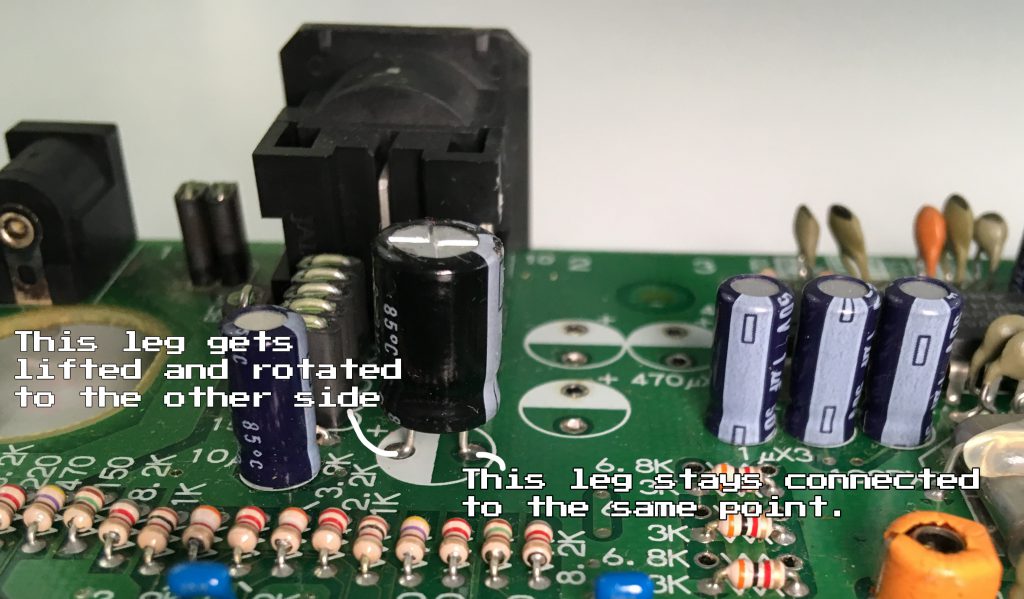
Lastly, solder the wire that you ran through the hole, to the positive input side of the capacitor you just rotated. Then snip any excess. 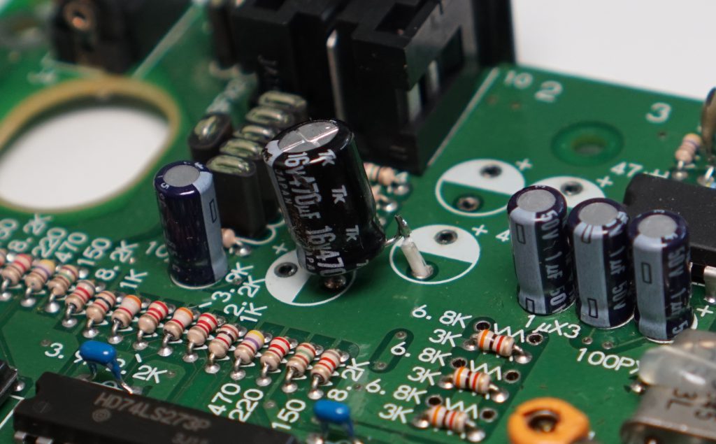


 NeoGeoAES3-6_RemoveRGBcomponents.jpg


