SNES:1CHIP Mods: Difference between revisions
| Line 26: | Line 26: | ||
## Attach output wires with a 750 ohm resistor on the Red, Green, and Blue lines to the RGB pins of the multi-out as shown below. | ## Attach output wires with a 750 ohm resistor on the Red, Green, and Blue lines to the RGB pins of the multi-out as shown below. | ||
## Attach 5V and Ground wires to motherboard and amp board as shown below. | ## Attach 5V and Ground wires to motherboard and amp board as shown below. | ||
# | #:[[File:1CHIPBypass-07.jpg|400px]] | ||
Since all 1CHIP's already have S-Video run to the board, the S-Video pads will not be used. The THS7374 low-pass filter can manipulated by shorting the LPF jumper. | Since all 1CHIP's already have S-Video run to the board, the S-Video pads will not be used. The THS7374 low-pass filter can manipulated by shorting the LPF jumper. | ||
Revision as of 04:08, 13 July 2022
Brightness Fix

All 1CHIP consoles output a signal that's too bright. This can result in an image that's slightly washed out, or shows signs of "ringing". In fact, it's possible that this is a big part of the reason some people think SNES Mini's look better then 1CHIP's. Luckily, the fix is _extremely_ easy!
- Disassemble the 1CHIP console and flip the board over.
- Locate the "R6", "R7" and "R8" RGB via holes
- Solder three 750 Ohm resistors to the holes and then solder all of them to the ground point shown in the picture.
- Trim any of the resistors that are sticking out the other end.
1CHIP-03 CSYNC Fix
There are three revisions of the 1CHIP motherboard: SNS-CPU-1CHIP-01, SNS-CPU-1CHIP-02 and SNS-CPU-1CHIP-03. The "03" revision does not have csync run to the multi-out. You can use these consoles without a modification, simply by using an RGB SCART cable that gets sync from luma. You can restore csync on these consoles by using a simple jumper wire, however that doesn't seem to be the best solution, as it's missing circuitry found in the other 1CHIP revisions: RetroRGB Migration:snescsync
If you have a 1CHIP-03, you'll want to consider using a sync-on-luma cable, restoring the entire circuit on the motherboard, or using an RGB bypass board that includes the full csync circuit.
1CHIP RGB Bypass
Even though the 1CHIP consoles already output high quality RGB, you still might want to bypass the onboard amp and use a different one.

You can use a Voultar's SNES 1CHIP/Mini RGB Bypass Kit or you can create a DIY RGB Amp board.
- Remove the motherboard and locate the multi-out pins on the bottom of the board.
- If using a pre-made board, place the amp chip over the multi-out pins and solder all the connections.
- Right near the multi-out, you'll find resistors labeled R9, R15, R16 and R17 and a capacitor labeled C46.
- De-solder these components to remove the RGBS connection to the multi-out. If you have a SNS-CPU-1CHIP-03, R9 and C46 will already be removed.
- Solder wires from the RGB vias (holes) to the RGB amp input pins.
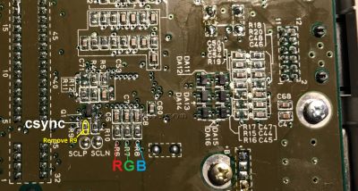
- Solder a wire from the CSSYNC via shown in the picture above to the RGB amp CSYNC input pin.
- If using a DIY board:
- Attach output wires with a 750 ohm resistor on the Red, Green, and Blue lines to the RGB pins of the multi-out as shown below.
- Attach 5V and Ground wires to motherboard and amp board as shown below.


Since all 1CHIP's already have S-Video run to the board, the S-Video pads will not be used. The THS7374 low-pass filter can manipulated by shorting the LPF jumper.