SNES:1CHIP Mods: Difference between revisions
mNo edit summary |
m (→Ghosting Fix) |
||
| (35 intermediate revisions by 2 users not shown) | |||
| Line 1: | Line 1: | ||
==Brightness Fix== | ==Brightness Fix== | ||
[[File:1CHIPBrightnessAdjustment.jpg|thumb|End Result.]] | [[File:1CHIPBrightnessAdjustment.jpg|thumb|End Result.]] | ||
All 1CHIP consoles output a signal that's too bright. This can result in an image that's slightly washed out | All 1CHIP consoles output a signal that's too bright. This can result in an image that's slightly washed out. In fact, it's possible that this is a big part of the reason some people think SNES Mini's look better then 1CHIP's. Luckily, the fix is extremely easy! | ||
# Disassemble the 1CHIP console and flip the board over. | |||
# Locate the "R6", "R7" and "R8" RGB via holes | |||
# Solder three 750 Ohm resistors to the via holes and then solder all of them to the ground point shown in the picture. | |||
# Trim any of the resistors that are sticking out the other end. | |||
Alternatively a single SMD resistor on the PCB can be replaced to reduce output current on the DAC. On an unmodified 1CHIP SNES R3 (next to C11) can be replaced with a 1.84 to 1.87 kOhm resistor to fix levels to the correct values. When the SNES is already modded with borti's RGB Bypass (and probably Voultar's, since they're very similar) replacing R3 on the board with a 1.74 kOhm Resistor will correct brightness. | |||
<br clear=all> | |||
==Ghosting Fix== | |||
[[File:SNESRestoreMay2020_Ghosting-Cap.jpg|thumb|Location of C11.]] | |||
While the SNES 1CHIP's have sharper video, one of the drawbacks is a "ghosting" or "ringing" effect that can ''sometimes'' be seen in certain screens. While it's not too big of a deal, it was enough to bother some people and luckily a fix was found. Simply replace C11 on any 1CHIP or mini console with a different value and the ghosting goes away. | |||
* [https://console5.com/store/0-47uf-470nf-10-35v-x7r-ceramic-capacitor-smd-surface-mount-snes-c11.html 1CHIP Ghosting Cap (0.47uF, 35V, 0805 size)] | |||
* [https://console5.com/store/0-47uf-470nf-10-35v-0603-x7r-ceramic-capacitor-smd-surface-mount-snes-mini.html SNES Mini Ghosting Cap (0.47uF, 35V, 0603 size)] | |||
<br clear=all> | |||
==1CHIP-03 CSYNC Fix== | ==1CHIP-03 CSYNC Fix== | ||
There are three revisions of the 1CHIP motherboard: SNS-CPU-1CHIP-01, SNS-CPU-1CHIP-02 and SNS-CPU-1CHIP-03. The "03" revision does not have | There are three revisions of the 1CHIP motherboard: SNS-CPU-1CHIP-01, SNS-CPU-1CHIP-02 and SNS-CPU-1CHIP-03. The "03" revision does not have CSYNC run to the multi-out. You can use RGB video output on these consoles without a modification simply by using an RGB SCART cable that gets sync from luma. | ||
Alternatively, you can restore CSYNC on these consoles by using a simple jumper wire from [[:Media:1CHIP-03-csync.jpg|the left pad of R12 to the left pad of R9]], however the 1CHIP-03 is also missing the following components which are required for proper CSYNC: | |||
[[File:1CHIP-01vs1CHIP-03csyncComponents.jpg|600px]] | |||
{| class="wikitable" | |||
! Component !! Value | |||
|- | |||
| Q1 || C2412 transistor. | |||
|- | |||
| R9 || 1.8kΩ | |||
|- | |||
| R10 || 3.3kΩ | |||
|- | |||
| R11 || 300Ω | |||
|- | |||
| R12 || 100Ω | |||
|- | |||
| C46 || 330pF | |||
|} | |||
If you have a 1CHIP-03, you'll want to consider using a sync-on-luma cable, restoring the entire circuit on the motherboard, or using an RGB bypass board that includes the full CSYNC circuit. A kit with the missing components can be found on [https://console5.com/store/super-nintendo-sns-cpu-1chip-03-csync-restore-repair-kit-c-sync.html Console5]. | |||
== 1CHIP RGB Bypass == | |||
Even though the 1CHIP consoles already output high quality RGB, you still might want to bypass the onboard amp and use a different one for a cleaner picture. Since all 1CHIP's already have S-Video run to the board, the S-Video pads will not be used. The THS7374 low-pass filter can manipulated by shorting the LPF pads. | |||
The following instructions are for Voultar's RGB Bypass, instructions for borti's RGB Bypass can be found [https://github.com/borti4938/SNES_RGB_Bypass at his Github] and at [https://videogameperfection.com/products/nintendo-rgb-bypass-amp-revision-4-1b-vgp/ Videogameperfection]. | |||
[[File:SNESTHS7374Installed.jpg|thumb|right|A finished RGB Bypass mod using a Voultar board.]] | [[File:SNESTHS7374Installed.jpg|thumb|right|A finished RGB Bypass mod using a Voultar board.]] | ||
* Required Materials: | |||
** Soldering equipment and 26-30AWG Wire | |||
** Three 750 ohm resistors (if brightness fix not already performed) | |||
** Three 75 ohm resistors | |||
** [https://voultar.com/index.php?route=product/product&product_id=88 Voultar's SNES 1CHIP/Mini RGB Bypass Kit] or you a [[RetroRGB_Migration:Thsamps|DIY RGB Amp]] board. | |||
# Remove the motherboard and locate the multi-out pins on the bottom of the board. | |||
#* If using a pre-made board, place the amp chip over the multi-out pins and solder all the connections. | |||
# Right near the multi-out, you'll find resistors labeled R15, R16 and R17. | |||
# De-solder these components to remove the RGBS connection to the multi-out. | |||
# If not present from doing the brightness fix separately: Insert a <u>750</u> ohm resistor into each of the three vias (holes), solder them in place, then solder all three to the nearby ground pad as shown below. Be sure to trim the leads off of the other side. <br> [[File:1CHIPBypass-11.jpg|400px]] | |||
# Solder wires onto the via side of the red (R6), green (R7), and blue (R8) resistors (as shown in the picture above) to the RGB amp input pins. | |||
# If using a DIY board: | |||
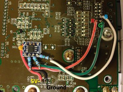
## Attach output wires with a <u>75</u> ohm resistor on the Red, Green, and Blue lines to the RGB pins of the multi-out as shown below. | |||
## Attach 5V and Ground wires to motherboard and amp board as shown below. <br> [[File:1CHIPBypass-07.jpg|400px]] | |||
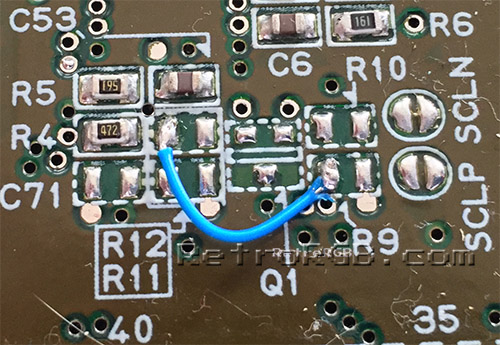
# If you have a SNS-CPU-1CHIP-03, you will need to solder a wire between these two pads to restore CSYNC to the multi-out port. <br> [[File:1CHIP-03-csync.jpg]] | |||
== References == | |||
[1] https://circuit-board.de/forum/index.php/Thread/4999-1-Chip-SNES-viel-bessere-Bildqualit%C3%A4t-Thread-inklusive-Ghosting-und-Helligkeits/?postID=668177#post668177 [https://circuit--board-de.translate.goog/forum/index.php/Thread/4999-1-Chip-SNES-viel-bessere-Bildqualit%C3%A4t-Thread-inklusive-Ghosting-und-Helligkeits/?postID=668177&_x_tr_sl=de&_x_tr_tl=en&_x_tr_hl=de&_x_tr_pto=wapp#post668177 / Google Translation] | |||
[2] https://github.com/borti4938/SNES_RGB_Bypass#brightness | |||
Latest revision as of 17:46, 24 September 2023
Brightness Fix

All 1CHIP consoles output a signal that's too bright. This can result in an image that's slightly washed out. In fact, it's possible that this is a big part of the reason some people think SNES Mini's look better then 1CHIP's. Luckily, the fix is extremely easy!
- Disassemble the 1CHIP console and flip the board over.
- Locate the "R6", "R7" and "R8" RGB via holes
- Solder three 750 Ohm resistors to the via holes and then solder all of them to the ground point shown in the picture.
- Trim any of the resistors that are sticking out the other end.
Alternatively a single SMD resistor on the PCB can be replaced to reduce output current on the DAC. On an unmodified 1CHIP SNES R3 (next to C11) can be replaced with a 1.84 to 1.87 kOhm resistor to fix levels to the correct values. When the SNES is already modded with borti's RGB Bypass (and probably Voultar's, since they're very similar) replacing R3 on the board with a 1.74 kOhm Resistor will correct brightness.
Ghosting Fix

While the SNES 1CHIP's have sharper video, one of the drawbacks is a "ghosting" or "ringing" effect that can sometimes be seen in certain screens. While it's not too big of a deal, it was enough to bother some people and luckily a fix was found. Simply replace C11 on any 1CHIP or mini console with a different value and the ghosting goes away.
1CHIP-03 CSYNC Fix
There are three revisions of the 1CHIP motherboard: SNS-CPU-1CHIP-01, SNS-CPU-1CHIP-02 and SNS-CPU-1CHIP-03. The "03" revision does not have CSYNC run to the multi-out. You can use RGB video output on these consoles without a modification simply by using an RGB SCART cable that gets sync from luma.
Alternatively, you can restore CSYNC on these consoles by using a simple jumper wire from the left pad of R12 to the left pad of R9, however the 1CHIP-03 is also missing the following components which are required for proper CSYNC:

| Component | Value |
|---|---|
| Q1 | C2412 transistor. |
| R9 | 1.8kΩ |
| R10 | 3.3kΩ |
| R11 | 300Ω |
| R12 | 100Ω |
| C46 | 330pF |
If you have a 1CHIP-03, you'll want to consider using a sync-on-luma cable, restoring the entire circuit on the motherboard, or using an RGB bypass board that includes the full CSYNC circuit. A kit with the missing components can be found on Console5.
1CHIP RGB Bypass
Even though the 1CHIP consoles already output high quality RGB, you still might want to bypass the onboard amp and use a different one for a cleaner picture. Since all 1CHIP's already have S-Video run to the board, the S-Video pads will not be used. The THS7374 low-pass filter can manipulated by shorting the LPF pads.
The following instructions are for Voultar's RGB Bypass, instructions for borti's RGB Bypass can be found at his Github and at Videogameperfection.

- Required Materials:
- Soldering equipment and 26-30AWG Wire
- Three 750 ohm resistors (if brightness fix not already performed)
- Three 75 ohm resistors
- Voultar's SNES 1CHIP/Mini RGB Bypass Kit or you a DIY RGB Amp board.
- Remove the motherboard and locate the multi-out pins on the bottom of the board.
- If using a pre-made board, place the amp chip over the multi-out pins and solder all the connections.
- Right near the multi-out, you'll find resistors labeled R15, R16 and R17.
- De-solder these components to remove the RGBS connection to the multi-out.
- If not present from doing the brightness fix separately: Insert a 750 ohm resistor into each of the three vias (holes), solder them in place, then solder all three to the nearby ground pad as shown below. Be sure to trim the leads off of the other side.
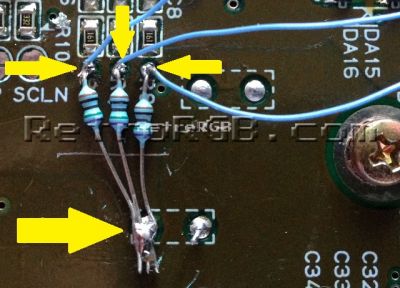
- Solder wires onto the via side of the red (R6), green (R7), and blue (R8) resistors (as shown in the picture above) to the RGB amp input pins.
- If using a DIY board:
- Attach output wires with a 75 ohm resistor on the Red, Green, and Blue lines to the RGB pins of the multi-out as shown below.
- Attach 5V and Ground wires to motherboard and amp board as shown below.
- If you have a SNS-CPU-1CHIP-03, you will need to solder a wire between these two pads to restore CSYNC to the multi-out port.


References
[1] https://circuit-board.de/forum/index.php/Thread/4999-1-Chip-SNES-viel-bessere-Bildqualit%C3%A4t-Thread-inklusive-Ghosting-und-Helligkeits/?postID=668177#post668177 / Google Translation