SNES:2CHIP YPbPr Mod
The video encoder found on the early SNES revisions (prior to the use of the S-RGB encoder) contains input and output pins for color difference signals (commonly referred to as YPbPr or Y/R-Y/B-Y). The color difference output signals of the encoder chip are connected to the input pins to encode the signals for S-Video and Composite video. It is possible to use the color difference output pins of the S-ENC encoder chip to add YPbPr outputs to these SNES consoles. However, the signals must be amplified and DC filtered before they can be connected to a display.
Compatible Revisions
This mod can only be performed on consoles containing the BA6592F or S-ENC encoder chip. The chip is present in the following console revisions:
- SHVC-CPU-01
- SNS-CPU-GPM-01
- SNS-CPU-GPM-02
- SNSP-CPU-01
- SNSP-CPU-02
Any revisions other than the ones listed contain the S-RGB encoder, which lacks color difference output pins and therefore is not compatible with this mod. Serial numbers beginning with UN272 or less are most likely to be compatible with this mod.
Parts and Tools Needed
- Parts
- Leaded solder
- Flux
- 28 AWG hook-up wire (color coded wires recommended)
- Video Amplifier consisting of the following
- Amplifier PCB (available on OSHPark) or perfboard
- 2x 1n4148 diodes
- 2x NPN transistors (i.e. 2n3904, SS8050, KSC945, etc)
- 2x 220uF 6.3v capacitors
- 2x 75 ohm resistors
- Output connector(s) of choice
- 3.5mm TRRS panel mount jack - for mounting either next to the power jack or in place of the RF modulator jack if removing the RF module. Use a 3x RCA to 3.5mm breakout cable for connection to your display.
- 3x RCA panel mount jacks - for mounting on the left side of the rear of the SNES case, only for revisions other than the SHVC-CPU-01 due to the sound board being in the way.
- Kapton tape or electrical tape
- Double-sided tape
- Tools
- 4.5 mm Gamebit screwdriver
- JIS/Philips screwdriver
- Soldering iron
- Multimeter
- Flush cutters
- Wire strippers
- Drill
- 1/8 inch twist drill bit
- 1/4 inch step drill bit (recommended) or twist drill bit
Procedure
- Completely disassemble the SNES console.
- Locate the video encoder chip labeled either BA6592F or S-ENC. Solder a red wire onto pin 1 and a blue wire onto pin 24.
- Solder a green wire onto pin 7 of the AV multi-out connector.
- Solder a yellow wire onto a 5V source (AV multi-out pin 10 or the output of the voltage regulator should work).
- Solder a black wire onto a ground source (AV multi-out pins 5 or 6 or the ground of the voltage regulator should work).
- Reinstall the heatsink and bottom shield of the SNES onto the motherboard, making sure not to pinch the wires coming from the bottom of the board in the process.
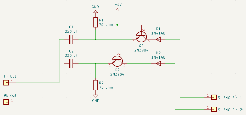
- Assemble your amplifier board using the schematic shown below. If using the specially designed PCB, jumper R3. It is an optional attenuation resistor spot for Luma.
- Place kapton/electrical tape onto the portion of the heatsink covering the RF modulator.
- Place kapton/electrical tape onto the bottom of your amplifier board, then place double-sided tape onto the same side.
- Peel of the film layer of the double-sided tape and place the board onto the heatsink portion you've place the kapton/electrical tape onto.
- Solder the wires coming from the board to the appropriate inputs of the amplifier.
- Black wire - GND
- Yellow wire - 5V
- Red wire: Pr
- Blue wire: Pb
- Green wire: Y (or solder the wire directly to your Y jack instead of on the board.)
- Drill the hole(s) for your jack(s) onto the appropriate place(s) of the bottom shell. The number of holes you need to drill as well as the location of the hole(s) will depend on the jack type you plan on using.
- Solder a set of four wires onto your jacks - One for ground and three for the video signals. If using a 3.5mm TRRS jack, it would be a good idea to use your multimeter to probe the pins of the jack that lead to the RCA connectors on your cable to determine where the wires should go and what they're for. If you're not using colored wire, use colored markers for identification of the wires.
- Install the jack(s) onto the bottom shell for your SNES console.
- Install the motherboard onto the bottom shell, making sure the wires coming from the bottom of the board don't get pinched. Note that the two long screws go to the cartridge connector and the third long screw (for the SHVC revision) goes to the sound board.
- Reinstall the top RF shield, controller ports, and power switch.
- With the motherboard installed, solder the jack wires onto the output pads for your amplifier using the reference guide above.
- Once you have everything wired up, it would be a good idea to test your SNES before reassembly to ensure that everything was installed correctly.
- If the console passed testing, it would be a good time to unplug it and finish assembling it. The eject lever is the hardest part to reinstall, therefore it is recommended to reinstall it after you've tested the console, that way you don't have to deal with reinstalling it twice in the event something is wrong with the mod.
