SNES:SNES Jr Pre-Assembled S-RGB Mod: Difference between revisions
Jump to navigation
Jump to search
No edit summary |
mNo edit summary |
||
| (6 intermediate revisions by 2 users not shown) | |||
| Line 1: | Line 1: | ||
[[File:VoultarSRGBboardV2.jpg|thumb]] | |||
[[File:VoultarSRGBboardV2.jpg]] | This guide shows you how to enable RGB and S-Video output on a SNES Mini / Jr using its built-in RGB amp (the 'S-RGB' chip) and a pre-assembled PCB that connects all the components. If you plan on using the S-RGB Encoder, this is definitely the method recommended. The brightness fix that other mods require is included with this mod. | ||
== Required Materials == | |||
* [http://voultar.com Voultar's Custom S-RGB Board] | |||
* The 4.5mm tool that opens the SNES | |||
* Philips head screwdriver | |||
* Soldering iron, solder, and flux | |||
* 26-30 AWG wire | |||
== Installation == | |||
== | |||
The mod is pretty easy, however soldering to the S-RGB chip can be extremely challenging. It's recommended beginners use an amp bypass mod for ease of installation, however if you're willing to solder to the small points this will work perfectly: | The mod is pretty easy, however soldering to the S-RGB chip can be extremely challenging. It's recommended beginners use an amp bypass mod for ease of installation, however if you're willing to solder to the small points this will work perfectly: | ||
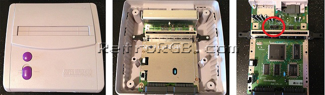
# Disassemble the console, remove the heatsink, and locate the S-RGB chip: <br> [[File:SNESMiniRGBModPage02.jpg]] | |||
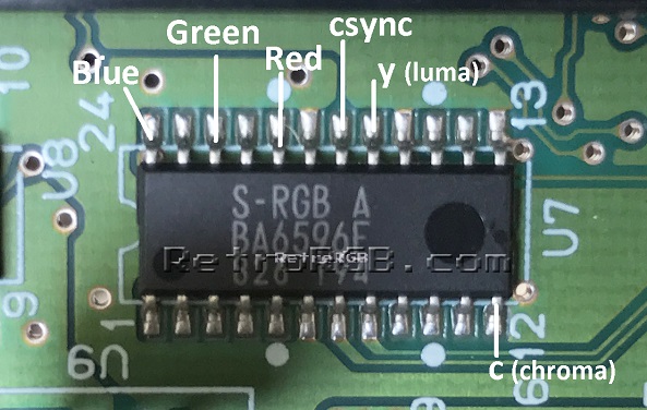
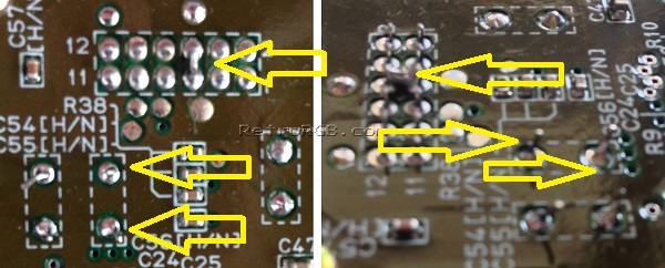
# Solder six wires to the pins on the “S-RGB A” chip as shown below. It's recommended to use heatshrink tubing to keep the wires together and also protect them from touching any other components. | |||
#* These are extremely small pins and very difficult for people who aren't experienced at soldering to work on. Use a soldering tip that's extremely thin, as well as very thin solder. Make sure to "tin" each pin and each wire before trying to solder them together. it's also recommended to add flux to each of the pins before tinning, as it makes soldering to them much easier: <br> [[File:S-RGB_RGBsYC.jpg]] | |||
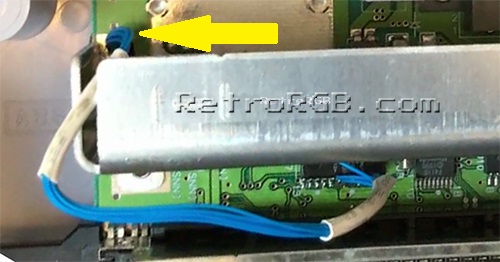
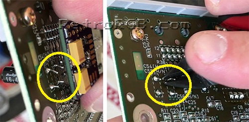
# Rreplace the heaksink and run the cables through the hole pictured below on the left: <br> [[File:S-RGB_WireRun.jpg]] | |||
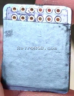
# It's recommended to add non-conductive tape to the bottom of the circuit board to prevent shorting out on other components: <br> [[File:SNES_Mod_Tape.jpg]] | |||
# Prepare to mount the circuit board over the multi-out pins. You may notice that there's a few larger components sticking up. If so, it's okay to snip them. Also, some SNES Mini's come from the factory with the two ground pins soldered together. If your system has this, you could either cut the solder in the middle (be really careful not to damage the pins), or use a solder-removing method (de-soldering iron, solder wick, etc) to remove it. <br> [[File:SNESMiniMultiOutInterference.jpg]] <br> [[File:SNES_Multi-out_Component_Interference.jpg]] | |||
# Place the board over the multi-out connections and solder the multi-out pins to the board. Then solder wires from the bottom RGB pads to the vias (holes) marked below. Flux will make soldering to those holes much easier. <br> [[File:SNES_S-RGBboard_InstallPoints.jpg]] | |||
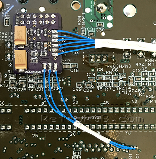
# Cut the RGBs / YC cables to size and solder them to the corresponding pins on the board. It's preferred to use heat shrink tubing to keep them all in place. <br> [[File:SNES_S-RGBboard_Installed.jpg]] | |||
# Reassemble and test it! | |||
Latest revision as of 14:29, 31 July 2022

This guide shows you how to enable RGB and S-Video output on a SNES Mini / Jr using its built-in RGB amp (the 'S-RGB' chip) and a pre-assembled PCB that connects all the components. If you plan on using the S-RGB Encoder, this is definitely the method recommended. The brightness fix that other mods require is included with this mod.
Required Materials
- Voultar's Custom S-RGB Board
- The 4.5mm tool that opens the SNES
- Philips head screwdriver
- Soldering iron, solder, and flux
- 26-30 AWG wire
Installation
The mod is pretty easy, however soldering to the S-RGB chip can be extremely challenging. It's recommended beginners use an amp bypass mod for ease of installation, however if you're willing to solder to the small points this will work perfectly:
- Disassemble the console, remove the heatsink, and locate the S-RGB chip:
- Solder six wires to the pins on the “S-RGB A” chip as shown below. It's recommended to use heatshrink tubing to keep the wires together and also protect them from touching any other components.
- These are extremely small pins and very difficult for people who aren't experienced at soldering to work on. Use a soldering tip that's extremely thin, as well as very thin solder. Make sure to "tin" each pin and each wire before trying to solder them together. it's also recommended to add flux to each of the pins before tinning, as it makes soldering to them much easier:
- These are extremely small pins and very difficult for people who aren't experienced at soldering to work on. Use a soldering tip that's extremely thin, as well as very thin solder. Make sure to "tin" each pin and each wire before trying to solder them together. it's also recommended to add flux to each of the pins before tinning, as it makes soldering to them much easier:
- Rreplace the heaksink and run the cables through the hole pictured below on the left:
- It's recommended to add non-conductive tape to the bottom of the circuit board to prevent shorting out on other components:
- Prepare to mount the circuit board over the multi-out pins. You may notice that there's a few larger components sticking up. If so, it's okay to snip them. Also, some SNES Mini's come from the factory with the two ground pins soldered together. If your system has this, you could either cut the solder in the middle (be really careful not to damage the pins), or use a solder-removing method (de-soldering iron, solder wick, etc) to remove it.
- Place the board over the multi-out connections and solder the multi-out pins to the board. Then solder wires from the bottom RGB pads to the vias (holes) marked below. Flux will make soldering to those holes much easier.

- Cut the RGBs / YC cables to size and solder them to the corresponding pins on the board. It's preferred to use heat shrink tubing to keep them all in place.
- Reassemble and test it!


